Functions
6-245
7SA6 Manual
C53000-G1176-C156-2
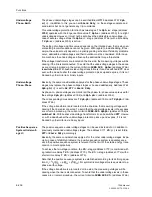
case the fault location is also calculated if for example a different protection device
cleared the fault. For a fault outside the protected line, the fault location information is
not always correct, as the measured values can be distorted by e.g. intermediate in-
feeds.
To calculate the distance to fault in kilometres or miles, the device requires the reac-
tance per unit length data in
Ω
/km or
Ω
/mile. For correct indication of the fault location
in % of line length, the correct line length should also be entered. These setting pa-
rameters were already applied with the plant data (Section 6.1.3 under “General Line
Data”).
A prerequisite for the correct indication of the fault location furthermore is that the other
parameters that influence the calculation of the distance to fault have also been set
correctly. These are the addresses (refer also to Sub-section 6.1.3)
1116
RE/RL(Z1)
,
1117
XE/XL(Z1)
or
1120
K0(Z1)
,
1121
PHI(K0(Z1))
.
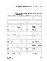
If the parallel line compensation is used, the address
3805
must be set to
Paral.Line Comp
=
Yes
; the presetting is
No
. Further prerequisites are that
•
the earth current of the parallel line has been connected to the fourth current input
I
4
with the correct polarity and
•
the parameter for the fourth current input
I4 transformer
has been set to
In
paral. line
(address
220
) in the “power system data 1” (refer also to Sub-sec-
tion 6.1.1 under “Current Transformer Connection”) and
•
the current transformer ratio
I4/Iph CT
(address
221
) in the “power system data
1” has been set correctly (refer also to Sub-section 6.1.1 under “Current Trans-
former Connection”) and
•
the mutual impedances
RM/RL ParalLine
and
XM/XL ParalLine
(addresses
1126
and
1127
) have been set correctly in the general protection data (“power sys-
tem data 2”, refer to Sub-section 6.1.3).
If load compensation is applied to single-phase faults in double-fed lines of an earthed
system, set
Yes
in address
3806
Load Compensat.
. In case high fault resistances
are expected for single-phase faults, e.g. at overhead lines without overhead earth
wire or unfavourable footing of the towers, this will improve the accuracy of the dis-
tance calculation.
If the fault location is required to be output as BCD-code, set the maximum time period
the data should be available at the outputs using address
3811
Tmax OUTPUT BCD
.
If a new fault occurs, the data are terminated immediately. Allocate the corresponding
output relays as “stored” if a longer time period is desired for the output. Once a fault
occurred the data will be latched until the memory is reset or a new fault is registered.
Summary of Contents for siprotec 7SA6
Page 2: ...Siemens Aktiengesellschaft Book No C53000 G1176 C156 2 ...
Page 18: ...xviii 7SA6 Manual C53000 G1176 C156 2 ...
Page 32: ...Introduction 1 14 7SA6 Manual C53000 G1176 C156 2 ...
Page 82: ...Hardware and Connections 2 50 7SA6 Manual C53000 G1176 C156 2 ...
Page 119: ...SIPROTEC 4 Devices 4 25 7SA6 Manual C53000 G1176 C156 2 Figure 4 20 CFC Logic example ...
Page 190: ...Configuration 5 62 7SA6 Manual C53000 G1176 C156 2 ...
Page 652: ...Installation and Commissioning 8 78 7SA6 Manual C53000 G1176 C156 2 ...
Page 724: ...Technical Data 10 56 7SA6 Manual C53000 G1176 C156 ...
Page 800: ...Appendix A 76 7SA6 Manual C53000 G1176 C156 2 ...
Page 866: ...Appendix B 66 7SA6 Manual C53000 G1176 C156 2 ...

