SIPROTEC
®
4 Devices
4-16
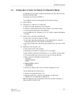
7SA6 Manual
C53000-G1176-C156-2
4.5
Manual Overwrite / Tagging
Manual Overwrite
If the breaker/switch position is not available from the switch-gear, the status of the
switchgear device can be manually set to the actual present position using the opera-
tor control panel:
Main Menu
→
Control
→
Breaker/Switch
→
Man. Over-
write
. The simulated switching status is used for interlocking checks, and for auto-
matically initiated switching operations.
Set Status
For convenience during commissioning or at other times, decoupling of the informa-
tion exchange between the switchgear and the protective device may be desired for a
short period, without disconnecting the wires. This function is activated using the op-
erator control panel:
Main Menu
→
Control
→
Breaker/Switch
→
Set Status
.
Tagging
To identify unusual operating conditions in the power system, tagging can be done.
The tagging can, for example, be entered as additional operating conditions in inter-
locking checks, which are set up with CFC. Tagging is configured in the same way as
for operating devices.
•
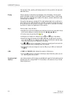
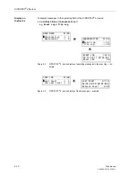
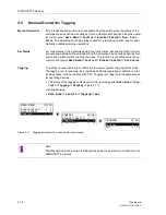
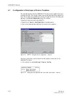
The status of the tagging is displayed on the operating panel,
Main Menu
→
Con-
trol
→
Tagging
→
Display
(Figure 4-11),
or changed using
•
Main Menu
→
Control
→
Tagging
→
Set
.
Figure 4-11
Tagging equipment from the operator control panel
TAGGING 01/02
---------------------
Display –> 1
Set –> 2
CONTROL 02/03
---------------------
Breaker/Switch –> 1
Tagging –> 2
Interlock –> 3
MAIN MENU 03/05
--------------------
Annunciation –> 1
Measurement –> 2
Control –> 3
Note:
The Manual Overwrite function is always done using the operator control panel on the
SIPROTEC
®
4 devices.
Summary of Contents for siprotec 7SA6
Page 2: ...Siemens Aktiengesellschaft Book No C53000 G1176 C156 2 ...
Page 18: ...xviii 7SA6 Manual C53000 G1176 C156 2 ...
Page 32: ...Introduction 1 14 7SA6 Manual C53000 G1176 C156 2 ...
Page 82: ...Hardware and Connections 2 50 7SA6 Manual C53000 G1176 C156 2 ...
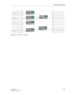
Page 119: ...SIPROTEC 4 Devices 4 25 7SA6 Manual C53000 G1176 C156 2 Figure 4 20 CFC Logic example ...
Page 190: ...Configuration 5 62 7SA6 Manual C53000 G1176 C156 2 ...
Page 652: ...Installation and Commissioning 8 78 7SA6 Manual C53000 G1176 C156 2 ...
Page 724: ...Technical Data 10 56 7SA6 Manual C53000 G1176 C156 ...
Page 800: ...Appendix A 76 7SA6 Manual C53000 G1176 C156 2 ...
Page 866: ...Appendix B 66 7SA6 Manual C53000 G1176 C156 2 ...


