Introduction
1-5
7SA6 Manual
C53000-G1176-C156-2
1.2
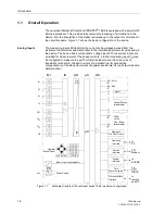
Applications
The numerical Distance Protection SIPROTEC
®
7SA6 is a fast and selective
protection device for overhead lines and cables with single- and multi-ended infeeds
in radial, ring or any type of meshed systems with insulation ratings. The system
starpoint can be earthed, resonant-earthed or isolated.
The device incorporates the functions which are normally required for the protection
of an overhead line feeder and is therefore capable of universal application. It may
also be applied as time graded back-up protection to all types of comparison
protection schemes used on lines, transformers, generators, motors and busbars of
all voltage levels.
The devices located at the ends of the protected zone exchange measuring
information via protection data interfaces using dedicated communication links
(usually fibre optic cables) or a communication network. If the 7SA6 devices are
equipped with a protection data interface, they can be applied for an object with
2 ends. Lines with three terminals (teed feeders) require at least one device with two
protection data interfaces.
Protection
Functions
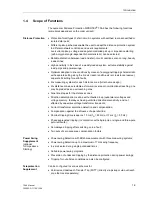
Recognition of the distance to fault with distance protection measurement, is the basic
function of the device. In particular for complex multiphase faults, the distance
protection has a non-switched 6-impedance-loops design (fullscheme). Different
pickup schemes enable a good adaption to system conditions and the user
philosophy. The influence of wrong distance measurement due to parallel lines can be
compensated by feeding the earth current of the parallel line to the relay. Parallel line
compensation can be used for distance protection as well as for the fault locator. It
may be supplemented by teleprotection using various signal transmission schemes
(for fast tripping on 100 % of the line length). In addition, an earth fault protection (for
high resistance earth faults, ordering option) is available, which may be directional,
non-directional and may also be incorporated in signal transmission. On lines with
weak or no infeed at one line end, it is possible to achieve fast tripping at both line ends
by means of the signal transmission scheme. Subsequent to energizing the line onto
a fault which may be located along the entire line length, it is possible to achieve a non-
delayed trip signal.
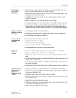
In the event of a failure of the measured voltages due to a fault in the secondary
circuits (e.g. trip of the voltage transformer mcb or a fuse) the device can automatically
revert to an emergency operation with an integrated time delayed overcurrent
protection, until the measured voltage again becomes available. The overcurrent
protection consists of three definite time overcurrent stages and an inverse time
(IDMT) stage. For the IDMT stage, a number of characteristics based on various
standards are available. The stages can be combined according to the user’s
requirements. Alternatively, the time delayed overcurrent protection may be used as
back-up time delayed overcurrent protection, i.e. it functions independent and in
parallel to the distance protection.
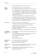
Depending on the version ordered, most short-circuit protection functions may also trip
single-pole. It may work in co-operation with an integrated automatic reclosure
(available as an option) with which single-pole, three-pole or single and three-pole
automatic reclosure as well as several interrupt cycles are possible on overhead lines.
Before reclosure after three-pole tripping, the permissibility of the reclosure can be
checked by voltage and/or synchronization check by the device. It is possible to
connect an external automatic reclosure and/or synchronization device as well as
double protection with one or two automatic reclosure functions.
Summary of Contents for siprotec 7SA6
Page 2: ...Siemens Aktiengesellschaft Book No C53000 G1176 C156 2 ...
Page 18: ...xviii 7SA6 Manual C53000 G1176 C156 2 ...
Page 32: ...Introduction 1 14 7SA6 Manual C53000 G1176 C156 2 ...
Page 82: ...Hardware and Connections 2 50 7SA6 Manual C53000 G1176 C156 2 ...
Page 119: ...SIPROTEC 4 Devices 4 25 7SA6 Manual C53000 G1176 C156 2 Figure 4 20 CFC Logic example ...
Page 190: ...Configuration 5 62 7SA6 Manual C53000 G1176 C156 2 ...
Page 652: ...Installation and Commissioning 8 78 7SA6 Manual C53000 G1176 C156 2 ...
Page 724: ...Technical Data 10 56 7SA6 Manual C53000 G1176 C156 ...
Page 800: ...Appendix A 76 7SA6 Manual C53000 G1176 C156 2 ...
Page 866: ...Appendix B 66 7SA6 Manual C53000 G1176 C156 2 ...

