Functions
6-249
7SA6 Manual
C53000-G1176-C156-2
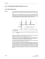
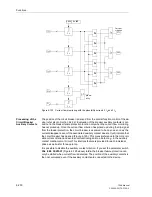
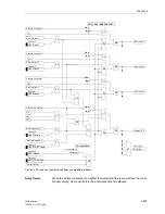
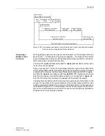
Figure 6-121 Simplified function diagram of circuit breaker failure protection controlled by
circuit breaker auxiliary contact
Current Flow
Monitoring
Each of the phase currents and an additional plausibility current (see below) are fil-
tered by numerical filter algorithms so that only the fundamental frequency is used for
further evaluation.
Special features recognise the instant of current interruption. With sinusoidal currents,
current interruption is detected after approx.10 ms. With d.c. transient current compo-
nents present in the fault current and/or in the current transformer secondary circuit
after interruption (e.g. current transformers with linearized core) or if the current trans-
formers are saturated by the d.c. component in the fault current, it can take one a.c.
cycle before the disappearance of the primary current is reliably detected.
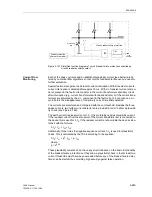
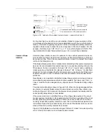
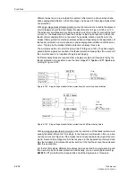
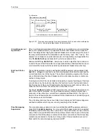
The currents are monitored and compared with the set threshold. Besides the three
phase currents, two further current detectors are provided in order to allow a plausibil-
ity check (see Figure 6-122).
The earth current (residual current
I
E
= 3·
I
0
) is preferably used as plausibility current.
If the residual current from the star-point of the current transformer set is connected to
the device this is used for 3·
I
0
. If the residual current is not available the device calcu-
lates it with the formula
3·
I
0
=
I
L1
+
I
L2
+
I
L3
.
Additionally, three times the negative sequence current 3·
I
2
is used for plausibility
check. This is calculated by the 7SA6 according to the equation:
3·
I
2
=
I
L1
+ a
2
·
I
L2
+ a ·
I
L3
where
a = e
j120°
.
These plausibility currents do not have any direct influence on the basic functionality
of the breaker failure protection but they allow a plausibility check in that at least two
current thresholds must have been exceeded before any of the breaker failure delay
times can be started, thus providing high security against false operation.
&
L+
Feeder protection
Circuit breaker failure protection
(internal or external)
Protection
Feeder
trip
Trip
bus-bar
Bus-bar
T–BF
0
Summary of Contents for siprotec 7SA6
Page 2: ...Siemens Aktiengesellschaft Book No C53000 G1176 C156 2 ...
Page 18: ...xviii 7SA6 Manual C53000 G1176 C156 2 ...
Page 32: ...Introduction 1 14 7SA6 Manual C53000 G1176 C156 2 ...
Page 82: ...Hardware and Connections 2 50 7SA6 Manual C53000 G1176 C156 2 ...
Page 119: ...SIPROTEC 4 Devices 4 25 7SA6 Manual C53000 G1176 C156 2 Figure 4 20 CFC Logic example ...
Page 190: ...Configuration 5 62 7SA6 Manual C53000 G1176 C156 2 ...
Page 652: ...Installation and Commissioning 8 78 7SA6 Manual C53000 G1176 C156 2 ...
Page 724: ...Technical Data 10 56 7SA6 Manual C53000 G1176 C156 ...
Page 800: ...Appendix A 76 7SA6 Manual C53000 G1176 C156 2 ...
Page 866: ...Appendix B 66 7SA6 Manual C53000 G1176 C156 2 ...

