Functions
6-287
7SA6 Manual
C53000-G1176-C156-2
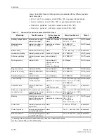
Symmetry
Monitoring
Address
2902A
BALANCE U-LIMIT
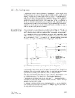
determines the voltage threshold (phase–
phase), above which the voltage symmetry monitoring is in service (refer to Figure 6-
141). Address
2903A
BAL. FACTOR U
is the corresponding symmetry factor, i.e. the
slope of the symmetry characteristic (Figure 6-141).
Address
2904A
BALANCE I LIMIT
determines the current threshold above which
the current symmetry monitoring is in service (refer also to Figure 6-140). Address
2905A
BAL. FACTOR I
is the corresponding symmetry factor, i.e. the slope of the
symmetry characteristic (Figure 6-140).
Summation
Monitoring
Address
2906A
Σ
I THRESHOLD
determines the current threshold above which the
current summation monitoring (refer to Figure 6-139) picks up (absolute value, only
referred to I
N
). The relative component (referred to the maximum conductor current)
for the pick-up of the current summation monitoring (Figure 6-139) is set in address
2907A
Σ
I FACTOR
.
Fuse Failure
Monitor
(Non-Symmetrical
Voltages)
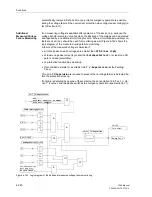
The settings of the fuse failure monitor for non-symmetrical measured voltage failure
(single- or two-phase) must be selected such that on the one hand reliable pick-up of
the monitoring is ensured in the case of loss of a single-phase voltage (address
2911A
FFM U>(min)
), while on the other hand a pick-up due to earth faults in an earthed
system is avoided. In accordance with this requirement, address
2912A
FFM I<
(max)
must be set sufficiently sensitive (below the smallest fault current due to earth
faults). In address
2910
FUSE FAIL MON.
, the fuse failure monitor can be switched
OFF
e.g. during non symmetrical testing.
Fuse Failure
Monitor
(Three-Phase)
In address
2913A
FFM U<max (3ph)
the minimum voltage threshold is set. If the
measured voltage drops below this threshold and a simultaneous current jump which
exceeds the limits according to address
2914A
FFM Idelta (3p)
is not detected
while all three phase currents are greater than the minimum current required for the
impedance measurement by the distance protection according to address
1202
Iph>
, a three phase measured voltage failure is recognized.
Measured Voltage
Failure Monitoring
The measured voltage failure monitoring (fuse failure monitor) can be activated by set-
ting address
2915
V-Supervision
to
with current supervision
or
with
current superv. and CBaux
and deactivated by setting it to
OFF
. Address
2916A
T V-Supervision
is used to set the waiting time of the voltage failure mon-
itoring.
Voltage Trans-
former Secondary
m.c.b.
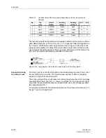
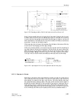
If a miniature circuit breaker for voltage transformers (VT mcb) is installed in the sec-
ondary circuit of the voltage transformers, the status is sent, via binary input, to the
device informing it about the position of the VT mcb. If a short-circuit in the secondary
side initiates the tripping of the VT mcb, the distance protection function has to be
blocked immediately. Otherwise a trip by the distance protection due to the lack of
measured voltage while load current is possible. The blocking must be faster than the
first stage of the distance protection.This requires an extremely short reaction time for
VT mcb (
≤
4 ms for 50 Hz,
≤
3 ms for 60 Hz nominal frequency). If this cannot be en-
sured, the reaction time is to be set under address
2921
T mcb
.
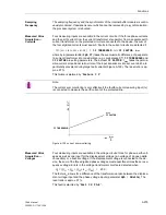
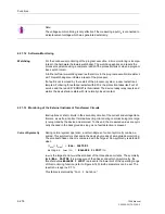
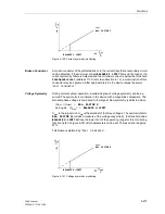
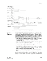
Note:
The current summation monitoring is only in service if the earth current of the protect-
ed feeder is connected to the fourth current measuring input (
I
4
) for earth currents.
Summary of Contents for siprotec 7SA6
Page 2: ...Siemens Aktiengesellschaft Book No C53000 G1176 C156 2 ...
Page 18: ...xviii 7SA6 Manual C53000 G1176 C156 2 ...
Page 32: ...Introduction 1 14 7SA6 Manual C53000 G1176 C156 2 ...
Page 82: ...Hardware and Connections 2 50 7SA6 Manual C53000 G1176 C156 2 ...
Page 119: ...SIPROTEC 4 Devices 4 25 7SA6 Manual C53000 G1176 C156 2 Figure 4 20 CFC Logic example ...
Page 190: ...Configuration 5 62 7SA6 Manual C53000 G1176 C156 2 ...
Page 652: ...Installation and Commissioning 8 78 7SA6 Manual C53000 G1176 C156 2 ...
Page 724: ...Technical Data 10 56 7SA6 Manual C53000 G1176 C156 ...
Page 800: ...Appendix A 76 7SA6 Manual C53000 G1176 C156 2 ...
Page 866: ...Appendix B 66 7SA6 Manual C53000 G1176 C156 2 ...


