Installation and Commissioning
8-16
7SA6 Manual
C53000-G1176-C156-2
Type of Contact for
Binary Outputs
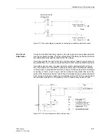
Input and output boards can contain relays of which the contact can be set as normally
closed or normally open contact. Therefore it is necessary to rearrange a jumper. Sec-
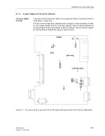
tion 8.1.3.3 “Input/Output Board C–I/O–1 and C–I/O–10” and “Input/Output Board B–
I/O–2” describes to which type of relays in which boards this applies.
Replacing
Interfaces
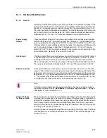
Only serial interfaces of devices for panel and cubicle mounting as well as of mounting
devices with detached operator panel are replaceable. For more details on this matter
refer to Subsubsection 8.1.3.4, “Replacing Interfaces”.
Termination of
Serial Interfaces
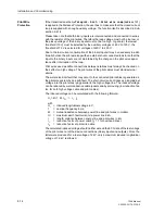
If the device is equipped with a serial RS485 port or Profibus, they must be terminated
with resistors at the last device on the bus to ensure reliable data transmission. For
this purpose, the printed circuit board of the central processor unit C-CPU-2 and the
RS485 or Profibus interface module are provided with terminating resistors that can
be connected to the system by means of jumpers. It is important to use only 1 of the
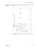
3 options. The position of the jumpers on the printed circuit board of the central proc-
essor unit C-CPU-2 is described in Subsubsection 8.1.3.3, see “Processor Board C-
CPU-2” and the position of the jumpers on the interface modules in Subsubsection
8.1.3.4. Both jumpers must always be plugged in the same way.
As delivered from the factory, the resistors are switched out.
8.1.3.2
Disassembly of the Device
If changes on jumper settings are required, e.g. control or removing and plugging of
jumpers or replacing printed circuit boards, proceed as follows:
o
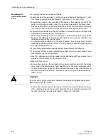
Prepare area of work. Provide a grounded mat for protecting components subject to
damage from electrostatic discharges (ESD). The following equipment is needed:
−
screwdriver with a 5 to 6 mm wide tip,
−
1 Philips screwdriver,
−
4.5 mm socket or nut driver.
Note:
If the 7SA6 performs trip circuit monitoring, two binary inputs, or one binary input and
a resistor, are connected in series. The pick-up voltage of these inputs must be less
than half of the nominal DC voltage of the trip circuit.
Caution!
Jumper-setting changes that affect nominal values of the device render the ordering
number and the corresponding nominal values on the nameplate sticker invalid. If
such changes are necessary, the changes should be clearly and fully noted on the de-
vice. Self adhesive stickers are available that can be used as replacement name-
plates.
Summary of Contents for siprotec 7SA6
Page 2: ...Siemens Aktiengesellschaft Book No C53000 G1176 C156 2 ...
Page 18: ...xviii 7SA6 Manual C53000 G1176 C156 2 ...
Page 32: ...Introduction 1 14 7SA6 Manual C53000 G1176 C156 2 ...
Page 82: ...Hardware and Connections 2 50 7SA6 Manual C53000 G1176 C156 2 ...
Page 119: ...SIPROTEC 4 Devices 4 25 7SA6 Manual C53000 G1176 C156 2 Figure 4 20 CFC Logic example ...
Page 190: ...Configuration 5 62 7SA6 Manual C53000 G1176 C156 2 ...
Page 652: ...Installation and Commissioning 8 78 7SA6 Manual C53000 G1176 C156 2 ...
Page 724: ...Technical Data 10 56 7SA6 Manual C53000 G1176 C156 ...
Page 800: ...Appendix A 76 7SA6 Manual C53000 G1176 C156 2 ...
Page 866: ...Appendix B 66 7SA6 Manual C53000 G1176 C156 2 ...

