Control During Operation
7-17
7SA6 Manual
C53000-G1176-C156-2
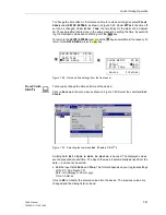
If the device is provided with analog outputs allocated to certain measured values dur-
ing the configuration according to Section 5.1, they can be read out in the display (e.g.
analog instrument).
Except for the current measured values the user can also read out the minimum, max-
imum and long-term measured values. The interval range for the calculation of the av-
erage value was set in Subsection 6.23.4.
The following average values are available:
•
I
L1
dmd, I
L2
dmd, I
L3
dmd, I
1
dmd: the measured values of the phase currents and
positive sequence system;
•
Pdmd, Pdmd Forw, Pdmd Rev: the active power as a whole and separately accord-
ing to Demand Forward and Demand Reverse;
•
Qdmd, QdmdForw, QdmdRev: the reactive power as a whole and separately ac-
cording to Demand Forward and Demand Reverse;
•
Sdmd: the apparent power.
For the following values both the minimum and the maximum values are available:
•
I
L1
, I
L2
, I
L3
, I
1
: phase currents and the positive sequence current;
•
I
L1
d, I
L2
d, I
L3
d, I
1
d: average values of the phase currents and the positive sequence
current;
•
U
L1–E
, U
L2–E
, U
L3–E
, U
1
: phase-earth voltages and positive sequence voltage;
•
U
L1–L2
, U
L2–L3
, U
L3–L1
, 3U
0
: phase-phase voltages and zero sequence voltage;
•
PForw, PRev, QForw, QRev, S: active and reactive power separately according to
Demand Forward and Demand Reverse as well as apparent power;
•
Pd, Qd, Sd: average values of active, reactive and apparent power;
Tabelle 7-2
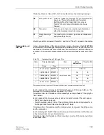
Operating measured values transmitted from the other end via protection data
interface in comparison with the local operating measured values
Data
prim. value
Geräte ADR
device address of the remote device
(absolute)
I
L1
, I
L2
, I
L3
remote
phase currents of the remote device
operating nominal current
1
)
I
L1
, I
L2
, I
L3
local
phase currents of the local device
operating nominal current
1
)
ϕ
(I
L1
),
ϕ
(I
L2
),
ϕ
(I
L3
)
phase angles between remote and
local phase currents
°
U
L1
, U
L2
, U
L3
remote
voltages of remote device
operating nominal voltage
/
√
3
2
)
U
L1
, U
L2
, U
L3
local
voltages of local device
operating nominal voltage
/
√
3
2
)
ϕ
(U
L1
),
ϕ
(U
L2
),
ϕ
(U
L3
) phase angles between remote and
local voltages
°
1
) for lines acc. to address
1104
(refer to Subsection 6.1.3),
2
) acc. to address
1103
(refer to Subsection 6.1.3)
Summary of Contents for siprotec 7SA6
Page 2: ...Siemens Aktiengesellschaft Book No C53000 G1176 C156 2 ...
Page 18: ...xviii 7SA6 Manual C53000 G1176 C156 2 ...
Page 32: ...Introduction 1 14 7SA6 Manual C53000 G1176 C156 2 ...
Page 82: ...Hardware and Connections 2 50 7SA6 Manual C53000 G1176 C156 2 ...
Page 119: ...SIPROTEC 4 Devices 4 25 7SA6 Manual C53000 G1176 C156 2 Figure 4 20 CFC Logic example ...
Page 190: ...Configuration 5 62 7SA6 Manual C53000 G1176 C156 2 ...
Page 652: ...Installation and Commissioning 8 78 7SA6 Manual C53000 G1176 C156 2 ...
Page 724: ...Technical Data 10 56 7SA6 Manual C53000 G1176 C156 ...
Page 800: ...Appendix A 76 7SA6 Manual C53000 G1176 C156 2 ...
Page 866: ...Appendix B 66 7SA6 Manual C53000 G1176 C156 2 ...

