Routine Checks and Maintenance
9-4
7SA6 Manual
C53000-G1176-C156-2
9.3
Maintenance
9.3.1
Replacing the Buffer Battery
The battery is used to retain the annunciation memories and fault recording data in the
event of an interruption of the power supply. The battery also maintains the internal
system clock with calendar after a loss of the power supply.
The battery is checked by the processor at regular intervals. If the capacity of the bat-
tery is found to be declining, an alarm is generated. The battery should be changed
when this alarm is given, or at the latest, after 10 years of service.
Recommended Battery:
Lithium Battery 3 V/1 Ah, Type CR 1/2 AA. For example:
−
VARTA Order Number 6127 101 501
9.3.1.1
Battery Change on Devices with Panel Flush Mounting and Cubicle Flush Mounting as well as
Panel Surface Mounting
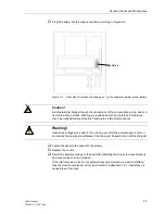
The battery is located near the front edge of the CPU printed circuit board. The front
panel of the device must be removed to change the battery.
To replace the battery:
o
Save the annunciations and fault records. These are the data under the Annunciation
sub-menu (all items in this sub-menu). The records and data are lost when the battery
is removed. The simplest and fastest method is to use the save feature in DIGSI
®
4
when the program is on-line.
Note:
All of the protective and control settings, including the input/output configuration
and the CFC logic, are not affected by a power supply interruption. The settings are
stored independently of the battery. The settings are not lost when the battery is re-
moved, nor are the settings affected if the device operates without a battery.
o
Have the replacement battery ready.
o
Isolate the power supply by opening the protective switches for both terminals.
Caution!
Do not short the battery! Do not reverse the polarity of the battery! Do not lay the bat-
tery on the ground mat used to protect components from electrostatic discharges! Do
not recharge the battery!
Caution!
Electrostatic discharges through the connections of the components, wiring, and con-
nectors must be avoided. Wearing a grounded wrist strap is preferred; otherwise, first
touch a grounded metal part before handling the internal components. Do not insert or
remove interface connectors under live conditions!
Summary of Contents for siprotec 7SA6
Page 2: ...Siemens Aktiengesellschaft Book No C53000 G1176 C156 2 ...
Page 18: ...xviii 7SA6 Manual C53000 G1176 C156 2 ...
Page 32: ...Introduction 1 14 7SA6 Manual C53000 G1176 C156 2 ...
Page 82: ...Hardware and Connections 2 50 7SA6 Manual C53000 G1176 C156 2 ...
Page 119: ...SIPROTEC 4 Devices 4 25 7SA6 Manual C53000 G1176 C156 2 Figure 4 20 CFC Logic example ...
Page 190: ...Configuration 5 62 7SA6 Manual C53000 G1176 C156 2 ...
Page 652: ...Installation and Commissioning 8 78 7SA6 Manual C53000 G1176 C156 2 ...
Page 724: ...Technical Data 10 56 7SA6 Manual C53000 G1176 C156 ...
Page 800: ...Appendix A 76 7SA6 Manual C53000 G1176 C156 2 ...
Page 866: ...Appendix B 66 7SA6 Manual C53000 G1176 C156 2 ...


