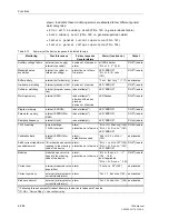
Functions
6-276
7SA6 Manual
C53000-G1176-C156-2
6.21.1.2 Software–Monitoring
Watchdog
For the continuous monitoring of the program execution, a time monitoring is incorpo-
rated in the hardware (hardware watchdog). The watchdog expires and resets the
processor system causing a complete reboot if the processor fails or when a program
loses synchronism.
A further software–watchdog ensures that errors in the program execution are detect-
ed. This watchdog also initiates a reset of the processor.
If a fault is not removed by the restart of the processor system, a new restart is at-
tempted. Following three failed restarts within 30 s the protection takes itself out of
service and the red LED “ERROR” is illuminated. The device ready relay resets and
alarms the device failure state with its normally closed contact.
6.21.1.3 Monitoring of the External Instrument Transformer Circuits
Interruptions or short circuits in the secondary circuits of the current and voltage trans-
formers, as well as incorrect terminations (important during commissioning) are large-
ly recognized by the device and alarmed. To this end, the measured values are cycli-
cally checked in the background as long as no fault detection is present.
Current Symmetry
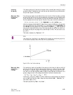
During normal system operation, a certain degree of current symmetry can be as-
sumed. This symmetry is checked in the device by means of a magnitude monitoring.
The smallest phase current is compared with the largest. Non-symmetry is detected
when
|
I
min
| / |
I
max
|
<
BAL. FACTOR I
as long as
I
max
/
I
N
>
BALANCE I LIMIT
/
I
N
I
max
is the largest and
I
min
is the smallest of the three phase currents. The symmetry
factor
BAL. FACTOR I
is a measure of the phase conductor non-symmetry, the
threshold value
BALANCE I LIMIT
represents the lower limit of the operating range
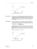
of this monitoring function (refer to Figure 6-140). Both parameters can be set. The
reset ratio is approx. 97 %.
This failure is alarmed by “
Fail I balance
”.
Note:
The voltage sum monitoring is only effective if the measuring input U
4
is connected to
a displacement voltage which was generated externally.
Summary of Contents for siprotec 7SA6
Page 2: ...Siemens Aktiengesellschaft Book No C53000 G1176 C156 2 ...
Page 18: ...xviii 7SA6 Manual C53000 G1176 C156 2 ...
Page 32: ...Introduction 1 14 7SA6 Manual C53000 G1176 C156 2 ...
Page 82: ...Hardware and Connections 2 50 7SA6 Manual C53000 G1176 C156 2 ...
Page 119: ...SIPROTEC 4 Devices 4 25 7SA6 Manual C53000 G1176 C156 2 Figure 4 20 CFC Logic example ...
Page 190: ...Configuration 5 62 7SA6 Manual C53000 G1176 C156 2 ...
Page 652: ...Installation and Commissioning 8 78 7SA6 Manual C53000 G1176 C156 2 ...
Page 724: ...Technical Data 10 56 7SA6 Manual C53000 G1176 C156 ...
Page 800: ...Appendix A 76 7SA6 Manual C53000 G1176 C156 2 ...
Page 866: ...Appendix B 66 7SA6 Manual C53000 G1176 C156 2 ...

