background image

 — 

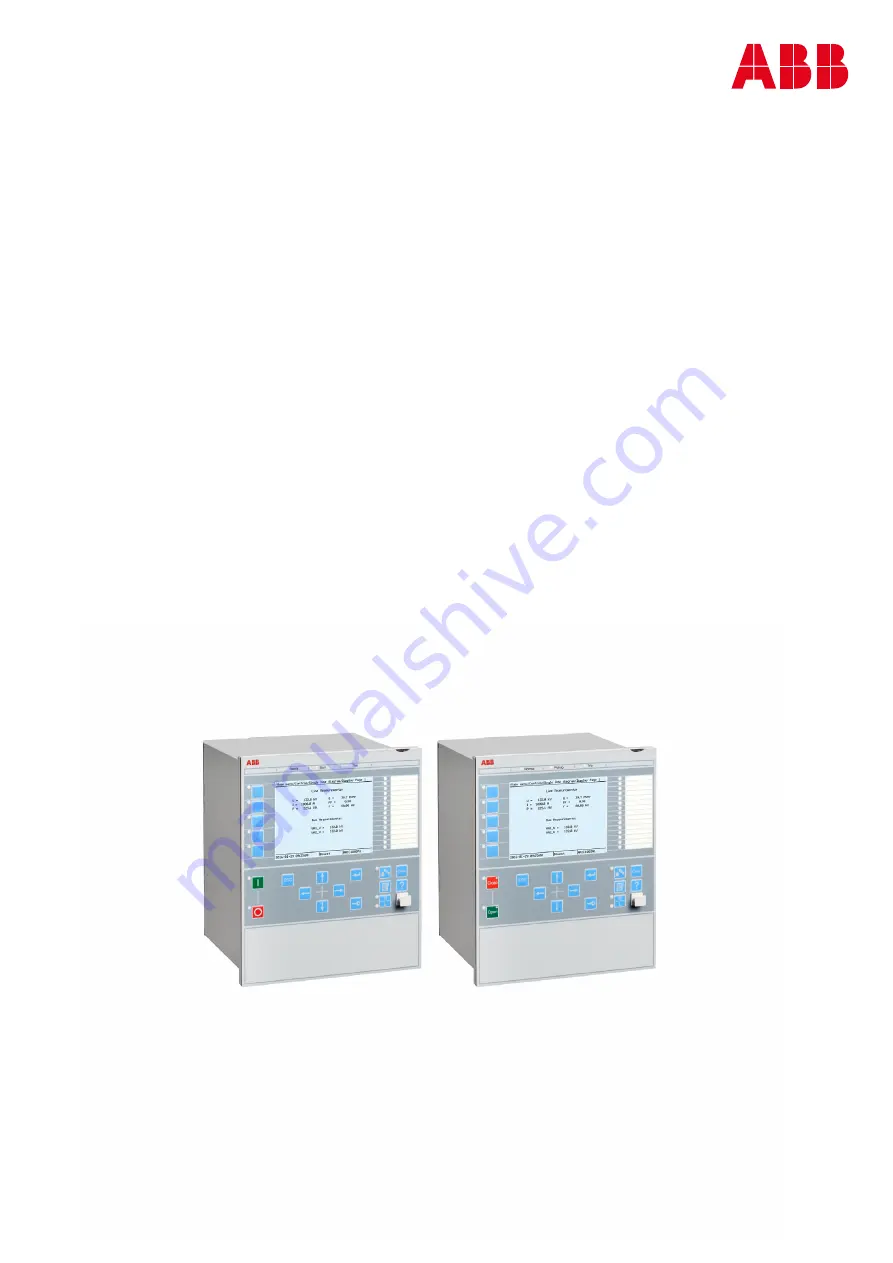
RELION®


650 SERIES

650 series 

Version 2.

1


Operation manual

Summary of Contents for RELION REL650

Page 1: ... RELION 650 SERIES 650 series Version 2 1 Operation manual ...

Page 2: ......

Page 3: ...Document ID 1MRK 500 125 UEN Issued March 2019 Revision A Product version 2 1 Copyright 2016 ABB All rights reserved ...

Page 4: ...erms of such license This product includes software developed by the OpenSSL Project for use in the OpenSSL Toolkit http www openssl org This product includes cryptographic software written developed by Eric Young eay cryptsoft com and Tim Hudson tjh cryptsoft com Trademarks ABB and Relion are registered trademarks of the ABB Group All other brand or product names mentioned in this document may be...

Page 5: ...product failure would create a risk for harm to property or persons including but not limited to personal injuries or death shall be the sole responsibility of the person or entity applying the equipment and those so responsible are hereby requested to ensure that all measures are taken to exclude or mitigate such risks This document has been carefully checked by ABB but deviations cannot be compl...

Page 6: ...nd concerning electrical equipment for use within specified voltage limits Low voltage directive 2006 95 EC This conformity is the result of tests conducted by ABB in accordance with the product standard EN 60255 26 for the EMC directive and with the product standards EN 60255 1 and EN 60255 27 for the low voltage directive The product is designed in accordance with the international standards of ...

Page 7: ...Section 4 Using the HMI 17 4 1 Using the local HMI 17 4 1 1 On screen keyboard 17 4 1 2 Logging on 18 4 1 3 Logging off 20 4 1 4 Turning the display backlight on 20 4 1 5 Identifying the device 20 4 1 6 Adjusting the display contrast 21 4 1 7 Navigating in the menu 21 4 1 7 1 Menu structure 21 4 1 7 2 Scrolling the display 22 4 1 7 3 Changing the default view 22 4 1 8 Browsing setting values 22 4 ...

Page 8: ...toring 34 6 1 3 1 Monitoring the IED remotely 34 6 1 4 Through fault monitoring report 35 6 1 4 1 Through fault monitoring tool 35 6 1 4 2 Through fault monitoring using local HMI 40 6 2 Resetting the IED 41 6 2 1 Clearing and acknowledging via the local HMI 41 6 3 Changing the IED functionality 42 6 3 1 Defining the setting group 42 6 3 1 1 Activating a setting group 42 6 3 1 2 Browsing and editi...

Page 9: ...ting user accounts and setting and changing passwords 48 7 3 1 1 Changing the password from the LHMI 48 7 3 2 Identifying IED application problems 49 7 3 2 1 Inspecting the wiring 49 Section 8 Glossary 51 Table of contents 3 Operation manual ...

Page 10: ...4 ...

Page 11: ...o identify disturbances and how to view calculated and measured power grid data to determine the cause of a fault 1 2 Intended audience GUID C9B8127F 5748 4BEA 9E4F CC762FE28A3A v10 This manual addresses the operator who operates the IED on a daily basis The operator must be trained in and have a basic knowledge of how to operate protection equipment The manual contains terms and expressions commo...

Page 12: ... the IED The manual provides procedures for mechanical and electrical installation The chapters are organized in the chronological order in which the IED should be installed The commissioning manual contains instructions on how to commission the IED The manual can also be used by system engineers and maintenance personnel for assistance during the testing phase The manual provides procedures for t...

Page 13: ...security deployment guideline describes the process for handling cyber security when communicating with the IED Certification Authorization with role based access control and product engineering for cyber security related events are described and sorted by function The guideline can be used as a technical reference during the engineering phase installation and commissioning phase and during normal...

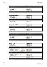
Page 14: ...to RET650 Document numbers Application manual 1MRK 504 158 UEN Commissioning manual 1MRK 504 160 UEN Product guide 1MRK 504 161 BEN Technical manual 1MRK 504 159 UEN Type test certificate 1MRK 504 161 TEN 650 series manuals Document numbers Operation manual 1MRK 500 125 UEN Engineering manual 1MRK 511 381 UEN Installation manual 1MRK 514 025 UEN Communication protocol manual DNP3 1MRK 511 374 UUS ...

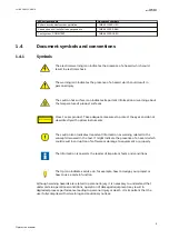
Page 15: ...e eyes and do not view directly with optical instruments The caution icon indicates important information or warning related to the concept discussed in the text It might indicate the presence of a hazard which could result in corruption of software or damage to equipment or property The information icon alerts the reader of important facts and conditions The tip icon indicates advice on for examp...

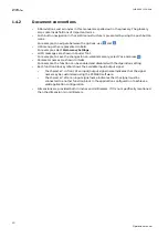
Page 16: ...mory select Yes and press Parameter names are shown in italics For example the function can be enabled and disabled with the Operation setting Each function block symbol shows the available input output signal the character in front of an input output signal name indicates that the signal name may be customized using the PCM600 software the character after an input signal name indicates that the s...

Page 17: ...ork related to the product GUID C9B6638A 57E7 4E05 9A33 A60E359C54AF v1 Only electrically skilled persons with the proper authorization and knowledge of any safety hazards are allowed to carry out the electrical installation M2366 2 v2 National and local electrical safety regulations must always be followed Working in a high voltage environment requires serious approach to avoid human injuries and...

Page 18: ...former with the secondary winding open will cause a massive potential build up that may damage the transformer and may cause injuries to humans M2372 2 v1 Never remove any screw from a powered IED or from a IED connected to powered circuitry Potentially lethal voltages and currents are present SEMOD168311 3 v1 Take adequate measures to protect the eyes Never look into the laser beam GUID 11CCF92B ...

Page 19: ...amage the module and IED circuitry M2698 2 v2 Take care to avoid electrical shock during installation and commissioning M2693 2 v1 Changing the active setting group will inevitably change the IEDs operation Be careful and check regulations before making the change 2 4 Note signs IP1497 1 v1 M19 2 v3 Observe the maximum allowed continuous current for the different current transformer inputs of the ...

Page 20: ...14 ...

Page 21: ...atically to evaluate their effect on our products and processes 3 2 Disposing of the IED AMU0600460 v6 Definitions and regulations of hazardous materials are country specific and change when the knowledge of materials increases The materials used in this product are typical for electric and electronic devices All parts used in this product are recyclable When disposing of an IED or its parts conta...

Page 22: ...16 ...

Page 23: ...switch off the auxiliary power supply to the IED before changes for example setting parameter or local remote control state changes are saved IEC13000282 1 en vsd GUID 6B1C3B17 FFD1 4D3C A50B 29524361C368 V1 EN US Figure 2 Saving changes animation Parameter saving is indicated by an animation in the lower right of the screen As long as this animation is shown saving is in progress 4 1 1 On screen ...

Page 24: ...ress to confirm IEC12000161 3 en vsd IEC12000161 V3 EN US Figure 4 Selecting the user name 4 Select OK on the on screen keyboard and press to stop editing the user name 5 Press to select the Password field and press to activate it An on screen keyboard is shown Each added character is shown for a short time then hidden with an asterisk character to enhance security You can end password editing at ...

Page 25: ...play IEC12000158 vsdx IEC12000158 V3 EN US Figure 6 Error message indicating an incorrect password If a false password is entered three times the login is blocked for that ID and the following message is displayed IEC13000283 vsdx GUID 3C167B43 074C 41E5 8FB1 A761A5A5D713 V2 EN US Figure 7 Error message indicating blocked ID The logon dialog appears if the attempted operation requires another leve...

Page 26: ... is ready for further operations If the panel has not been used for a predefined timeout period the backlight is switched off The user is logged out from the current user level after the display backlight has turned off The factory default for display timeout is 10 minutes The minimum is 1 minute The display returns to the default view and all unconfirmed operations for example parameter editing a...

Page 27: ... restored to set value for parameter ContrastLevel Set the parameter ContrastLevel via Main menu Configuration HMI Screen SCREEN 1 to permanently change the display contrast 4 1 7 Navigating in the menu AMU0600412 v7 Navigate the menus and change the display views on the screen with the keypad To move to the Main menu or default view press To move up or down in a menu press or To move downwards in...

Page 28: ...is Main menu unless set otherwise 1 Select Main menu Configuration HMI Screen SCREEN 1 and press 2 Change the default view with or 3 Press to confirm the selection 4 1 8 Browsing setting values GUID 81116DC8 1E66 4144 920F 07C79F1C76B0 v6 1 Select Main menu Settings IED Settings and press 2 Press and then to activate the setting group number selection IEC13000241 1 en vsd GUID 5196A07A 9DAF 4696 8...

Page 29: ...ss increases or decreases the value by a certain step For integer values the change is 1 10 100 or 1000 depending on the active digit For decimal values the change can be fractions 0 1 0 01 0 001 depending on the active digit For parameters with defined steps digits smaller than the step value cannot be edited 3 Press or to move the cursor to another digit 4 To select the minimum or maximum value ...

Page 30: ...15000063 vsdx IEC15000063 V1 EN US 4 Edit the string using the on screen keyboard 5 Select OK on the on screen keyboard or press while the string editing field is focused to accept the entered string is accepted and the editing dialog is closed 4 1 9 3 Editing enumerated values AMU0600417 v6 1 Activate the setting mode and select a setting When editing an enumerated value the selected value is sho...

Page 31: ...settings To leave the change setting mode select No or Yes in the Save changes dialog After changing the parameters marked with the IED restarts automatically for the changes to take effect 4 1 11 Clearing and acknowledging AMU0600425 v10 The Clear button is used to reset acknowledge or clear all messages and indications including LEDs and latched outputs as well as registers and recordings Press ...

Page 32: ...The help dialog is also closed when the display timeout expires IEC13000065 2 en vsd IEC13000065 V2 EN US Figure 18 Help menu Section 4 1MRK 500 125 UEN A Using the HMI 26 Operation manual ...

Page 33: ...y authorized and skilled personnel should analyze possible errors and decide on further actions Otherwise stored disturbance data can be lost 5 2 1 Disturbance recording triggering GUID 5569488B F930 4762 99CE 2863BEFB1947 v8 Disturbance recordings are normally triggered by IED applications when they detect fault events Disturbance recordings can also be triggered manually or periodically The manu...

Page 34: ...on or operating system and communication errors Further actions always depend on the cause of the error Only authorized and skilled personnel should analyze the errors and decide on further actions The IED records IED status data and events Document all the recorded data from the IED before resetting the tripping and IED lockout functions 5 2 5 Non operative functions GUID 752CDABC 4F21 4A02 AF77 ...

Page 35: ...g values for example via the LHMI The values in other setting groups should be known before editing a certain setting value After completing the editing of setting group values the new values are activated The user can either commit the edited values or discard them 5 3 2 IED settings for different operating conditions GUID 7328A918 CE00 4F97 B51F FD7FC63FD30D v5 IED settings can be designed for v...

Page 36: ...30 ...

Page 37: ... vsd GUID 6FC25881 990D 4288 8206 7F807044F572 V2 EN US Figure 19 Fault indication The internal event list is not updated dynamically To update the list leave the Internal events menu and then select it again 6 1 2 Recorded data GUID 1E9CFEC1 6245 4612 B637 821951B95D60 v7 The IED is provided with intelligent and flexible functionality that collects different kinds of data The recorded data gives ...

Page 38: ...E 1 1 Select Main menu Disturbance records 2 Select Manual Trig with or 3 Press to execute manual triggering IEC13000261 1 en vsd GUID D18A9DC0 4392 4BAF 86D0 C43F2714B428 V1 EN US Figure 20 Manual triggering The disturbance recorder is now triggered 6 1 2 2 Monitoring disturbance recorder data GUID CBA8221F A0F8 4043 98D7 577830F29F7F v6 Read individual disturbance recordings from the IED with th...

Page 39: ...6F5E45F 12FE 40E7 9C3F 8CA82DB8498C V1 EN US Figure 22 Disturbance record data categories 4 To select a category and view the items under it press or and then 6 1 2 3 Controlling and reading disturbance recorder data GUID E128266D 1DB5 4437 963F D3DE8FF0FF32 v7 Disturbance recorder data can be controlled and read with PCM600 For more information see PCM600 documentation 1MRK 500 125 UEN A Section ...

Page 40: ...s or to scroll the view IEC13000264 1 en vsd GUID 11970631 EFA2 429B B4A6 D7E28DC120B6 V1 EN US Figure 23 Monitoring events The event list is not updated dynamically To update the list leave the Events menu and then select it again 6 1 3 Remote monitoring GUID 4813E67F 5F17 48A7 A083 27E006A5B386 v1 The IED supports comprehensive remote monitoring 6 1 3 1 Monitoring the IED remotely GUID D1DA8B48 ...

Page 41: ...rting the through fault monitoring tool GUID 7BB279C0 D436 417D ACBE C0CBA55C0DD6 v1 Proceed as follows to start the through fault monitoring tool from the IED level 1 Right click on the Plant Structure of an IED 2 Select the Through Fault Monitoring from the context menu as shown in Figure 24 IEC18000083 1 en vsdx IEC18000083 V1 EN US Figure 24 Starting the through fault monitoring tool The throu...

Page 42: ...ult reports table contains the latest 100 records per function block instance IEC18000081 1 en vsdx IEC18000081 V1 EN US Figure 26 Through fault reports table As shown in Figure 26 the through fault reports table consist of Instance number Fault number and Date and time columns respectively The Instance number column contains data related to the function block instance number The Fault number colu...

Page 43: ...rmers The Winding 3 column is hidden and not shown in the report overview table The Winding 3 related data will have zero values corresponding to General and Name columns IEC18000082 1 en vsdx IEC18000082 V1 EN US Figure 27 Selected through fault report data table Reading through fault reports from the IED GUID B7414006 344C 46CE BFE7 FD707B672B92 v1 To read the through fault reports from the IED ...

Page 44: ...ing through fault reports from the IED GUID FAAA98A3 E5E7 4A01 BA1E BF8C35C86CCA v1 In order to delete through fault reports from the IED via PCM600 at function block instance level proceed as follows 1 Select the function block instance from the Through fault monitoring function selection combo box as shown in Figure 29 IEC18000086 1 en vsdx IEC18000086 V1 EN US Figure 29 Select function block in...

Page 45: ...ation pop up dialog box is displayed if external users CAM UAM are defined in the IED The roles with IEDCmd Advanced right are allowed to clear through fault reports from an IED via PCM600 Exporting through fault reports files GUID 63BAF274 FC37 4416 819B D9973FC103F4 v1 Proceed as follows to export through fault reports files from the IED via PCM600 1 Click on the export reports option from the t...

Page 46: ...rts those are grouped based on the instance can be found on the local HMI under Main menu Measurements Through fault reports The reports list contains date and time of the through fault and the latest report is displayed first As shown in Figure 35 the local HMI mapped inputs can be displayed by entering each through fault report IEC18000094 1 en vsdx IEC18000094 V1 EN US Figure 35 Local HMI throu...

Page 47: ...tion to U3P Event wise RMS voltage L2 The winding is based on the input connection to U3P Event wise RMS voltage L3 The winding is based on the input connection to U3P Multiple faults warning Number of faults Event wise maximum peak current Event wise RMS current Event wise I2t Event wise I2t in of set limit Delta I2t compared to prior fault Cumulative maximum peak current Cumulative I2t Cumulativ...

Page 48: ...setting parameter changes are saved 6 3 1 1 Activating a setting group AMU0600439 v8 IED settings are planned in advance for different operation conditions by calculating setting values to different setting groups The active setting group can be changed manually from the menu or by the PCM600 tool 1 Select Main menu Settings Active setting group SETGRPS 1 and press IEC13000235 1 en vsd GUID 9BC3D5...

Page 49: ... list depend on the configuration configured with PCM600 Figure 39 Selecting the function category 6 To browse the function blocks scroll the list with and Function blocks available depend on the application configuration To move back to the list press 7 To select a function block press Figure 40 Function block settings The character on the right indicates that the parameter belongs to a setting g...

Page 50: ...44 ...

Page 51: ...he error origin from IED s internal event list Main menu Diagnostics IED status General 2 Reboot the IED and recheck the supervision events to see if the fault has cleared 3 In case of persistent faults contact ABB for corrective actions 7 1 3 Identifying blocked functions GUID 012B4B88 F260 4B20 885F 998AD384D586 v2 1 Check the list of blocked functions from the LHMI under Main menu Diagnostics I...

Page 52: ...hen the value is 0 there is no communication link 7 1 4 2 Checking the time synchronization GUID CE54512E 06E3 4255 823C 1ACA122CC67E v6 Select Main menu Diagnostics IED status General and check the status of the time synchronization on Time synch The Time synch value is Ready when the synchronization is in order Note that the time synchronization source has to be activated Otherwise the value is ...

Page 53: ...ror One or more of the application threads are not in an expected state Internal Fail IEC 61850 Error IEC 61850 has not succeeded in some actions such as reading the configuration file or start up Internal Fail PSM1 Error A PSM card error has occurred The instance number is shown as part of the fault indication such as 1 in this example Internal Fail BIM3 Error A binary in module error has occurre...

Page 54: ...n is lost or time system has made a time reset Settings Changed Settings have been changed Setting Groups Changed Setting group has been changed 7 3 Correction procedures 7 3 1 Creating user accounts and setting and changing passwords GUID D3FA85BA 1E36 4F8B BD71 85C7AC46A0B4 v2 If Central Account Management is disabled in the IED user account creation initial password setting and password changin...

Page 55: ...t or voltage connections to IED terminals might be correct wrong polarity of one or more measurement transformers can cause problems Check the actual state of the connected binary inputs In LHMI select Main menu Test Binary input values Then navigate to the board with the actual binary input to be checked Check the actual state of the connected binary inputs through PCM600 see PCM600 documentation...

Page 56: ...al binary output relay to be operated forced 3 Select the BOn to be operated forced and use and or to operate the actual output relay Each BOn is represented by two signals The first signal in LHMI is the actual value 1 or 0 of the output and in PCM600 a lit or dimmed diode The second signal is the status Normal or Forced Forced status is only achieved when the BO is set to Forced or operated on t...

Page 57: ...ary output module BOS Binary outputs status BR External bistable relay BS British Standards BSR Binary signal transfer function receiver blocks BST Binary signal transfer function transmit blocks C37 94 IEEE ANSI protocol used when sending binary signals between IEDs CAN Controller Area Network ISO standard ISO 11898 for serial communication CB Circuit breaker CBM Combined backplane module CCITT C...

Page 58: ...ransformer CU Communication unit CVT or CCVT Capacitive voltage transformer DAR Delayed autoreclosing DARPA Defense Advanced Research Projects Agency The US developer of the TCP IP protocol etc DBDL Dead bus dead line DBLL Dead bus live line DC Direct current DFC Data flow control DFT Discrete Fourier transform DHCP Dynamic Host Configuration Protocol DIP switch Small switch mounted on a printed c...

Page 59: ...m GSAL Generic security application GSE Generic substation event HDLC protocol High level data link control protocol based on the HDLC standard HFBR connector type Plastic fiber connector HMI Human machine interface HSAR High speed autoreclosing HV High voltage HVDC High voltage direct current IDBS Integrating deadband supervision IEC International Electrical Committee IEC 60044 6 IEC Standard Ins...

Page 60: ...et switching protocol It provides packet routing fragmentation and reassembly through the data link layer 2 Ingression protection according to IEC 60529 IP 20 Ingression protection according to IEC 60529 level 20 IP 40 Ingression protection according to IEC 60529 level 40 IP 54 Ingression protection according to IEC 60529 level 54 IRF Internal failure signal IRIG B InterRange Instrumentation Group...

Page 61: ... PSM Power supply module PST Parameter setting tool within PCM600 PT ratio Potential transformer or voltage transformer ratio PUTT Permissive underreach transfer trip RASC Synchrocheck relay COMBIFLEX RCA Relay characteristic angle RISC Reduced instruction set computer RMS value Root mean square value RS422 A balanced serial interface for the transmission of digital data in point to point connecti...

Page 62: ...ce data TNC connector Threaded Neill Concelman a threaded constant impedance version of a BNC connector TP Trip recorded fault TPZ TPY TPX TPS Current transformer class according to IEC TRM Transformer Module This module transforms currents and voltages taken from the process into levels suitable for further signal processing TYP Type identification UMT User management tool Underreach A term used ...

Page 63: ...dervoltage WEI Weak end infeed logic VT Voltage transformer 3IO Three times zero sequence current Often referred to as the residual or the earth fault current 3UO Three times the zero sequence voltage Often referred to as the residual voltage or the neutral point voltage 1MRK 500 125 UEN A Section 8 Glossary 57 Operation manual ...

Page 64: ...58 ...

Page 65: ...59 ...

Page 66: ...B Substation Automation Products SE 721 59 Västerås Sweden Phone 46 0 21 32 50 00 www abb com protection control Copyright 2016 ABB All rights reserved Scan this QR code to visit our website 1MRK 500 125 UEN ...

Reviews: