


7.1.4.1
Checking the communication link operation
GUID-A1815C16-1AB7-4DEE-8E9B-0BF91DDEE72C v9
There are several different communication links on the product. First check that all
communication ports that are used for communication are turned on.
1.
the front communication port RJ-45.
1.1. Check that the uplink LED is lit with a steady green light.
The uplink LED is located on the LHMI above the RJ-45 communication port on the
left. The port is used for direct electrical communication to a PC connected via a
crossed-over Ethernet cable.
1.2. Check the communication status of the front port via the LHMI in Main menu/
Diagnostics/Communication/Ethernet status/Front port/FRONTSTATUS:1.
Check that the
LinkStatus value is 1, that is, the communication is working. When
the value is 0, there is no communication link.
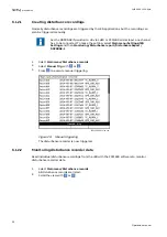
2.
the communication status of the rear ports via the LHMI in Main menu/Diagnostics/
Communication/Ethernet status/Access points
The communication ports on the rear side of the IED are for optical Ethernet via ST
connectors.
•
Check that the
LinkStatus value is 1, that is, the communication is working. When
the value is 0, there is no communication link.
7.1.4.2
Checking the time synchronization
GUID-CE54512E-06E3-4255-823C-1ACA122CC67E v6
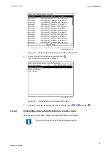
•
Select Main menu/Diagnostics/IED status/General and check the status of the time
synchronization on Time synch.
The
Time synch value is Ready when the synchronization is in order.
Note that the time synchronization source has to be activated. Otherwise
the value is always
Ready.
7.1.5
Diagnosing the IED status via the LHMI hint menu
GUID-7E8503E9-441B-487A-9CD7-B43463D1CAE5 v3
In order to help the user, there is an LHMI page labeled ‘Hints’. This page is located under Main
menu/Diagnostics/IED status/Hints. For each activated hint there is a headline. From the
headline view, an explanation page can be entered, giving the user more information and hints
about the particular topic.
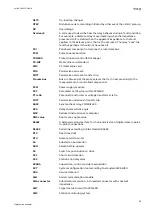
The supported list of hints are as follows:
Table 3:
Hint menu
Headline
Explanation
GOOSE is configured on a disabled port
At least one of the access points configured for
GOOSE is disabled. The port can be disabled either
through changing the access point operation to off
or by unchecking the GOOSE protocol from the
access point in the Ethernet configuration in PCM600
or LHMI.
Please enable GOOSE on access points: AP_FRONT,
AP_1
Section 7
1MRK 500 125-UEN A
Troubleshooting
46
Operation manual


