Functions
6-254
7SA6 Manual
C53000-G1176-C156-2
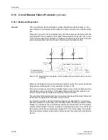
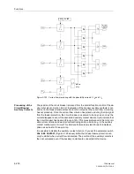
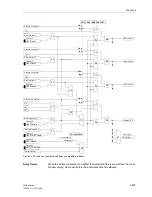
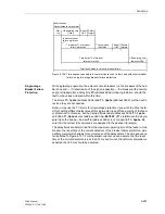
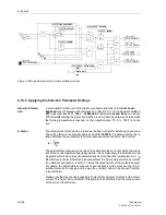
Figure 6-127 Breaker failure protection with phase segregated initiation — example for
initiation by an external protection device with release by a separate set of trip
contacts
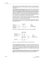
Initiation of a single-phase, e.g. “Start L1 only” is valid when the starting input (= trip
command of any feeder protection) appears for only this phase and current flow is de-
tected in at least this phase. If current flow is not detected, the auxiliary contact posi-
tion can be interrogated according to Figure 6-123, dependent on the setting (
Chk
BRK CONTACT
=
Yes
).
The auxiliary contact criterion is also processed for each individual breaker pole. If
however the breaker auxiliary contacts are not available for each individual breaker
pole, then a single-pole trip command is assumed to be executed only once the series
connection of the normally open (NO) auxiliary contacts is interrupted. This informa-
tion is provided to the breaker fail protection by the central function control of the de-
vice (refer to Section 6.22.2).
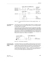
The three-phase starting signal “Start L123” is generated if trip signals appear in more
than one pole (regardless from which protection function). Phase segregated initiation
is then blocked. The input “
>BF Start w/o I
” (e.g. from Buchholz protection) op-
erates in three-phase mode as well. The function is the same as with common phase
initiation.
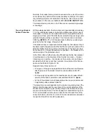
The additional release-signal “
>BF release
” (if assigned to a binary input) affects all
starting conditions. Initiation can be blocked via the binary input “
>BLOCK BrkFail
”
(e.g. during test of the feeder protection relay). Additionally, an internal blocking option
is provided.
7SA6
Trip L1
L+
external
prot. device
L–
>BF Start L1
Trip L1
Trip L2
>BF Start L2
Trip L2
Trip L3
>BF Start L3
Trip L3
>BF release
Summary of Contents for siprotec 7SA6
Page 2: ...Siemens Aktiengesellschaft Book No C53000 G1176 C156 2 ...
Page 18: ...xviii 7SA6 Manual C53000 G1176 C156 2 ...
Page 32: ...Introduction 1 14 7SA6 Manual C53000 G1176 C156 2 ...
Page 82: ...Hardware and Connections 2 50 7SA6 Manual C53000 G1176 C156 2 ...
Page 119: ...SIPROTEC 4 Devices 4 25 7SA6 Manual C53000 G1176 C156 2 Figure 4 20 CFC Logic example ...
Page 190: ...Configuration 5 62 7SA6 Manual C53000 G1176 C156 2 ...
Page 652: ...Installation and Commissioning 8 78 7SA6 Manual C53000 G1176 C156 2 ...
Page 724: ...Technical Data 10 56 7SA6 Manual C53000 G1176 C156 ...
Page 800: ...Appendix A 76 7SA6 Manual C53000 G1176 C156 2 ...
Page 866: ...Appendix B 66 7SA6 Manual C53000 G1176 C156 2 ...

