Control During Operation
7-50
7SA6 Manual
C53000-G1176-C156-2
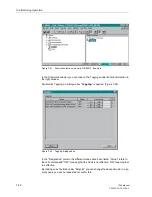
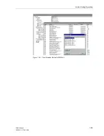
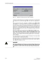
Figure 7-51
Dialog Box for Performing Control in DIGSI
®
4 (example)
A description of the switching device is displayed in the left column of the dialog field.
This represents the contents of the
Long Text
column within the configuration ma-
trix.
The actual position of the switch is displayed in the
Status
column (
OPEN
,
CLOSE
,
Intermediat
). The switching possibilities are displayed in the
Scheduled
column.
Four control fields are shown in the right part of the dialog field. If a check mark is dis-
played in one of these fields,
AB
(Access Block = Block Input Acquisition),
TB
(Trans-
mission Block = Serial Interface Blocked),
TR
(Manual Overwriting), and
CB
(Chatter
Block), the associated block function is set or the feedback indications of the device
have been simulated.
Normally, operating devices are switched in the
interlocked (Normal)
mode.
The configured interlocking conditions are checked before a control command is car-
ried out. As soon as a control command is entered in the
Scheduled
column, Pass-
word No. 1 for interlocked switching is requested for safety reasons. Further control
possibilities remain possible until the control dialog field is closed, or the switching
mode is changed.
If a control command is successfully executed, then the display of the actual condition
of the affected switch is updated in the window.
Operating resources can be switched without interlocking condition checks; however,
the correct Password No. 2 for non-interlocked switching must be entered. Mark the
option
Unlock
by clicking on the field.
DANGER!
Only highly qualified personnel who have an exact knowledge of the power sys-
tem conditions shall perform non-interlocked switching. Inappropriate switch-
ing operations can lead to death, serious personnel injury and property dam-
age.
Summary of Contents for siprotec 7SA6
Page 2: ...Siemens Aktiengesellschaft Book No C53000 G1176 C156 2 ...
Page 18: ...xviii 7SA6 Manual C53000 G1176 C156 2 ...
Page 32: ...Introduction 1 14 7SA6 Manual C53000 G1176 C156 2 ...
Page 82: ...Hardware and Connections 2 50 7SA6 Manual C53000 G1176 C156 2 ...
Page 119: ...SIPROTEC 4 Devices 4 25 7SA6 Manual C53000 G1176 C156 2 Figure 4 20 CFC Logic example ...
Page 190: ...Configuration 5 62 7SA6 Manual C53000 G1176 C156 2 ...
Page 652: ...Installation and Commissioning 8 78 7SA6 Manual C53000 G1176 C156 2 ...
Page 724: ...Technical Data 10 56 7SA6 Manual C53000 G1176 C156 ...
Page 800: ...Appendix A 76 7SA6 Manual C53000 G1176 C156 2 ...
Page 866: ...Appendix B 66 7SA6 Manual C53000 G1176 C156 2 ...


