Configuration
5-56
7SA6 Manual
C53000-G1176-C156-2
Other Interfaces
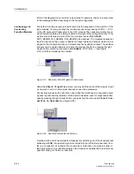
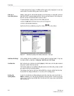
Enter specific settings and addresses to identify devices in the other tabs, if neces-
sary, or check the preset values.
Device addresses are used by the system to identify each device and must be unique
throughout the substation. Detailed instructions for setting the interfaces are available
in the “DIGSI
®
4 Communications” manual.
If you desire to expand or modify interfaces later, refer to the modification instructions
for the interfaces, and if necessary for the hardware, see also instructions in Sub-sec-
tion 8.1.3 of this manual.
Profibus FMS on
the PC
For a Profibus connection — if available — between a SIPROTEC
®
device and the
SICAM
®
SAS or DIGSI
®
4, a minimum transfer rate of 500 kBaud is recommended for
disturbance-free communication.
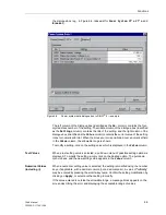
Signal Idle State
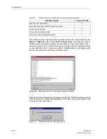
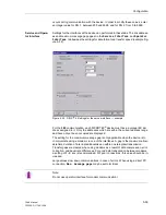
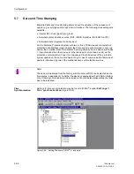
For optical connections, the signal idle state is preset for “light off.” Modification of the
signal idle state is accomplished in the tab for the interface settings (see Figure 5-53).
Figure 5-53
Settings for an optical interface — example
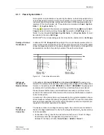
Reading and Modi-
fying Interface Set-
tings at the Device
Reading and partial modification of the most important interface settings is possible,
using the key-pad and display on the device panel. You may access the setting page
for the interface via
MAIN MENU
through
Settings
→
Setup/Extras
→
Serial
Ports
.
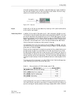
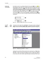
Under the sub-menu title
SERIAL PORTS
, you will find
Front
,
System
, and
Service
Port
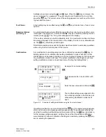
, and selections may be made using the
navigation button. By pressing the
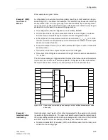
button, the sub-menu for a particular interface can be accessed. The display and
the ability to change settings directly at the device are the same at both the front and
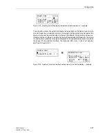
service interfaces. Figure 5-54 shows the data of the front (operator) interface, as an
example.
Summary of Contents for siprotec 7SA6
Page 2: ...Siemens Aktiengesellschaft Book No C53000 G1176 C156 2 ...
Page 18: ...xviii 7SA6 Manual C53000 G1176 C156 2 ...
Page 32: ...Introduction 1 14 7SA6 Manual C53000 G1176 C156 2 ...
Page 82: ...Hardware and Connections 2 50 7SA6 Manual C53000 G1176 C156 2 ...
Page 119: ...SIPROTEC 4 Devices 4 25 7SA6 Manual C53000 G1176 C156 2 Figure 4 20 CFC Logic example ...
Page 190: ...Configuration 5 62 7SA6 Manual C53000 G1176 C156 2 ...
Page 652: ...Installation and Commissioning 8 78 7SA6 Manual C53000 G1176 C156 2 ...
Page 724: ...Technical Data 10 56 7SA6 Manual C53000 G1176 C156 ...
Page 800: ...Appendix A 76 7SA6 Manual C53000 G1176 C156 2 ...
Page 866: ...Appendix B 66 7SA6 Manual C53000 G1176 C156 2 ...

