Functions
6-265
7SA6 Manual
C53000-G1176-C156-2
6.19
Thermal Overload Protection
6.19.1 Method of Operation
The thermal overload protection prevents damage to the protected object caused by
thermal overloading, particularly in case of transformers, rotating machines, power re-
actors and cables. It is in general not necessary for overhead lines, since no meaning-
ful overtemperature can be calculated because of the great variations in the environ-
mental conditions (temperature, wind). In this case, however, a current-dependent
alarm stage can signal an imminent overload.
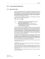
The unit computes the overtemperature according to a thermal single-body model as
per the following thermal differential equation
with
Θ
–
instantaneous overtemperature referred to the final temperature
rise for the maximum permissible line current
k ·
I
N
τ
th
–
thermal time constant for heating
k
–
k-factor which states the maximum permissible continuous
current referred to the rated current of the current transformers
I
–
currently measured r.m.s. current
I
N
–
rated current of current transformers
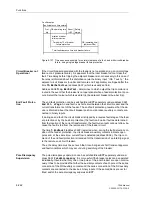
The solution of this equation under steady-state conditions is an e-function whose as-
ymptote shows the final overtemperature
Θ
end
. When the overtemperature reaches
the first settable temperature threshold
Θ
alarm
, which is below the final overtempera-
ture, a warning alarm is given in order to allow a timely load reduction. When the sec-
ond temperature threshold, i.e. the final overtemperature or tripping temperature, is
reached, the protected object is disconnected from the network. The overload protec-
tion can, however, also be set on
Alarm Only
. In this case only an alarm is output
when the final overtemperature is reached.
The overtemperature is calculated separately for each phase with a thermal replica
from the square of the associated phase current. This guarantees a true r.m.s. value
measurement and also includes the influence of harmonic content. A choice can be
made whether the maximum calculated overtemperature of the three phases, the av-
erage overtemperature, or the overtemperature calculated from the phase with maxi-
mum current should be decisive for evaluation of the thresholds.
The maximum permissible continuous thermal overload current
I
max
is described as a
multiple of the rated current
I
N
:
I
max
= k ·
I
N
In addition to the k-factor, the time constant
τ
th
as well as the alarm temperature
Θ
alarm
must be entered in the protection.
Apart from the thermal alarm stage, the overload protection also includes a current
overload alarm stage
I
alarm
, which can output an early warning that an overload cur-
rent is present, even if the overtemperature has not yet reached the alarm or trip over-
temperature values.
The overload protection can be blocked via a binary input. In doing so, the thermal im-
ages are also reset to zero.
d
Θ
dt
--------
1
τ
th
-------
Θ
⋅
+
1
τ
th
-------
I
k
I
⋅
N
-------------
è
ø
æ
ö
2
⋅
=
Summary of Contents for siprotec 7SA6
Page 2: ...Siemens Aktiengesellschaft Book No C53000 G1176 C156 2 ...
Page 18: ...xviii 7SA6 Manual C53000 G1176 C156 2 ...
Page 32: ...Introduction 1 14 7SA6 Manual C53000 G1176 C156 2 ...
Page 82: ...Hardware and Connections 2 50 7SA6 Manual C53000 G1176 C156 2 ...
Page 119: ...SIPROTEC 4 Devices 4 25 7SA6 Manual C53000 G1176 C156 2 Figure 4 20 CFC Logic example ...
Page 190: ...Configuration 5 62 7SA6 Manual C53000 G1176 C156 2 ...
Page 652: ...Installation and Commissioning 8 78 7SA6 Manual C53000 G1176 C156 2 ...
Page 724: ...Technical Data 10 56 7SA6 Manual C53000 G1176 C156 ...
Page 800: ...Appendix A 76 7SA6 Manual C53000 G1176 C156 2 ...
Page 866: ...Appendix B 66 7SA6 Manual C53000 G1176 C156 2 ...

