Configuration
5-45
7SA6 Manual
C53000-G1176-C156-2
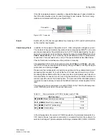
A few examples are given below.
Example 1 (MW):
Low Current
Monitor
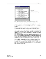
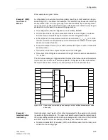
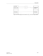
A configuration for low-current monitoring alarm (see Figure 5-42) which can be pro-
duced using CFC, should be a first example. This element may be used to detect op-
eration without load, or to recognize open circuited conditions. By connecting meas-
ured current values with a limit function via an OR function, an indication may be gen-
erated which can be used to cause switching operations.
•
The configuration sheet is assigned to task level MW_BEARB.
•
Four function modules (3 lower-value limit modules and an OR gate), are taken
from the function module library and copied into the configuration sheet.
•
In the left panel, the measurement values to be monitored (I
L1
, I
L2
, I
L3
in % of the
nominal current) are each selected and connected with the measured value inputs
of each limit module function.
•
A lower limit setpoint value (IL<) is linked with the limit inputs of each of three limit
sensor functions.
•
The limit value function outputs are passed on to the OR gate.
•
The output of the OR gate is connected to the right border column at annunciation
“
I< alarm
”.
The limit value message is triggered when the preset limit value is below the setpoint
(low current) in at least one of the three phases. The hysteresis of the limit values is
fixed and need not be entered (5 % of set point plus 0.5 % of nominal value).
Figure 5-42
Under-current monitoring as an example of user defined measurement value
processing
Example 2:
Isolation Switch
Interlocking
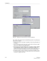
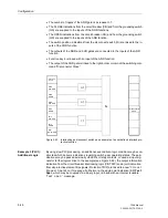
Interlocking logic (see Figure 5-43) is to be implemented for the operation of an isolat-
ing switch using function key 4. The user must take the switch position indications of
the corresponding isolation switch and the grounding switch into account. The CLOSE
and TRIP indications from the auxiliary contacts of each switch are used.
•
Function modules NOR (2 required), XOR, and AND are taken from the library and
copied into the working page.
FM:
Lower
Setpoint
Vo
l
Li
m
it
I<
alarm OUT
Measurement
IL1
FM:
Vo
l
Ann
u
n
ci
a
ti
on
B
O
Li
m
it
FM:
Vo
l
A
nnun
ci
ati
o
n
B
O
Li
m
it
Lower
Setpoint
Lower
Setpoint
FM:
Set points
IL<
Measurement
IL2
Set points
IL<
Set points
IL<
Measurement
IL3
A
nnu
n
ci
a
ti
on
B
O
>1
Summary of Contents for siprotec 7SA6
Page 2: ...Siemens Aktiengesellschaft Book No C53000 G1176 C156 2 ...
Page 18: ...xviii 7SA6 Manual C53000 G1176 C156 2 ...
Page 32: ...Introduction 1 14 7SA6 Manual C53000 G1176 C156 2 ...
Page 82: ...Hardware and Connections 2 50 7SA6 Manual C53000 G1176 C156 2 ...
Page 119: ...SIPROTEC 4 Devices 4 25 7SA6 Manual C53000 G1176 C156 2 Figure 4 20 CFC Logic example ...
Page 190: ...Configuration 5 62 7SA6 Manual C53000 G1176 C156 2 ...
Page 652: ...Installation and Commissioning 8 78 7SA6 Manual C53000 G1176 C156 2 ...
Page 724: ...Technical Data 10 56 7SA6 Manual C53000 G1176 C156 ...
Page 800: ...Appendix A 76 7SA6 Manual C53000 G1176 C156 2 ...
Page 866: ...Appendix B 66 7SA6 Manual C53000 G1176 C156 2 ...

