Functions
6-163
7SA6 Manual
C53000-G1176-C156-2
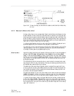
6.11.1 Method of Operation
Measured Values
The phase currents are fed to the device via the input transformers of the measuring
input. The residual current 3·
I
0
is either measured directly or calculated from the
phase currents, depending on the ordered device version and usage of the fourth cur-
rent input
I
4
of the device.
If
I
4
is connected in the current transformer star-point connection circuit the residual
(earth) current is directly available as a measured quantity.
If the device is supplied with the high sensitivity current input for
I
4
(ordered version),
this current
I
4
— under consideration of the factor
I4/Iph CT
(address
221
, refer to
Sub-section 6.1.1) of the power system data 1 — is used. As the linear range of this
measuring input is severely restricted in the high range (above approx. 1.6 A), this cur-
rent is only evaluated up to an amplitude of approx. 1 A. In the event of larger currents,
the device automatically switches over to the evaluation of the zero sequence current
calculated from the phase currents. Naturally, all three phase currents obtained from
a set of three star connected current transformers must be available and connected to
the device. The processing of the earth current is then also possible if very small as
well as large earth fault currents may occur.
If the fourth current input
I
4
is used e.g. for a power transformer star-point current or
for the earth current of a parallel line, the device derives the earth current from the
phase currents. Naturally in this case also all three phase currents derived from a set
of three star connected current transformers must be available and connected to the
device.
Definite Time High
Set Overcurrent
Stage I>>
Each phase current is numerically filtered and then compared with the set value
Iph>>
, the earth current with
3I0>>
. Currents above the associated pickup value are
detected and annunciated. After expiry of the associated time delays
T Iph>>
re-
spectively
T 3I0>>
a trip command is issued. The reset threshold is approx. 5 % be-
low the pick up threshold, but at least 1,5 % of rated current below the pick-up thresh-
old.
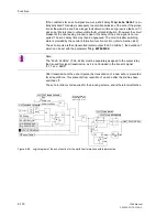
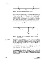
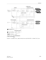
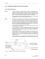
Figure 6-91 shows the logic diagram of the I>>–stages. They may be blocked via the
binary input
“>BLOCK O/C I>>
”. The binary input “
>O/C InstTRIP
” and the func-
tion module “Switch on to fault” are common to all stages and further described below.
They may, however, separately affect the phase and/or earth current stages. This is
accomplished with the following setting parameters:
•
I>> Telep/BI
(address
2614
), which determines whether a non-delayed trip of
this stage is possible (
Yes
) via the binary input “
>O/C InstTRIP
” or not (
No
)
•
I>> SOTF
(address
2615
), which determines whether non-delayed tripping of this
stage is possible (
Yes
) or not (
No
) following switching of the feeder on to a dead
fault.
Summary of Contents for siprotec 7SA6
Page 2: ...Siemens Aktiengesellschaft Book No C53000 G1176 C156 2 ...
Page 18: ...xviii 7SA6 Manual C53000 G1176 C156 2 ...
Page 32: ...Introduction 1 14 7SA6 Manual C53000 G1176 C156 2 ...
Page 82: ...Hardware and Connections 2 50 7SA6 Manual C53000 G1176 C156 2 ...
Page 119: ...SIPROTEC 4 Devices 4 25 7SA6 Manual C53000 G1176 C156 2 Figure 4 20 CFC Logic example ...
Page 190: ...Configuration 5 62 7SA6 Manual C53000 G1176 C156 2 ...
Page 652: ...Installation and Commissioning 8 78 7SA6 Manual C53000 G1176 C156 2 ...
Page 724: ...Technical Data 10 56 7SA6 Manual C53000 G1176 C156 ...
Page 800: ...Appendix A 76 7SA6 Manual C53000 G1176 C156 2 ...
Page 866: ...Appendix B 66 7SA6 Manual C53000 G1176 C156 2 ...

