Functions
6-205
7SA6 Manual
C53000-G1176-C156-2
6.14.2 Setting the function parameters
General
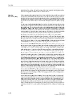
If no reclosure is required on the feeder to which the Distance Protection 7SA6 is ap-
plied (e.g. for cables, transformers, motors or similar), the automatic reclosure function
must be removed during configuration of the device (see Section 5.1, address
133
).
The automatic reclosure function is then completely disabled, i.e. the automatic re-
closure is not processed in the 7SA6. No signals regarding the reclosure function are
generated and the binary inputs for the automatic reclosure function are ignored. All
parameters for setting the automatic reclosure function are inaccessible and of no sig-
nificance. Tripping is always three-pole for all faults.
If, on the other hand, the internal automatic reclosure function is to be used, the type
of reclosure must be selected during the configuration of the functions (see Section
5.1) in address
133
Auto Reclose
and the
AR control mode
in address
134
.
Up to 8 reclosure attempts are allowed with the integrated automatic reclosure func-
tion in the 7SA6. Whereas the settings in the addresses
3401
to
3441
are common
to all reclosure cycles, the individual settings of the cycles are made from address
3450
onwards. It is therefore possible to set different individual parameters for the
first four reclose cycles. The parameters of the fourth cycle also apply to the fifth cycle
and onwards.
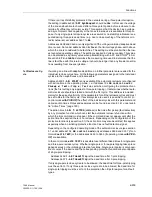
Under address
3401
AUTO RECLOSE
the automatic reclosure function can be
switched
On
or
Off
.
A prerequisite for automatic reclosure taking place after a trip due to a short-circuit is
that the circuit-breaker is ready for at least one TRIP–CLOSE–TRIP–cycle at the time
the automatic reclosure is started (i.e. at the time of the first trip command). The read-
iness of the circuit-breaker is signalled to the device through the binary input “
>CB1
Ready
” (F.No
371
). If no such signal is available, leave the setting under address
3402
CB? 1.TRIP
=
No
because no automatic reclosure would be possible at all oth-
erwise. If circuit-breaker readiness can be interrogated, the setting
CB? 1.TRIP
=
Yes
should be applied.
Furthermore the circuit-breaker ready state can also be interrogated prior to every re-
closure. This is set when setting the individual reclose cycles (see below).
To check if the circuit-breaker is ready again during the dead times, it is possible to set
a circuit-breaker–ready–monitor time under address
3409
CB TIME OUT
. This time
is set slightly longer than the recovery time of the circuit-breaker after a TRIP–
CLOSE–TRIP–cycle. If the circuit-breaker is not ready again by the time this timer ex-
pires, no reclosure takes place, the automatic reclosure function is blocked dynami-
cally.
Waiting for the circuit-breaker to be ready can lead to an increase of the dead times.
Interrogation of a synchro–check (if used) can also delay reclosure. To avoid uncon-
trolled prolongation it is possible to set a maximum prolongation of the dead time in
this case under address
3411A
T-DEAD EXT.
. This prolongation is unlimited if the
setting
∞
is applied. This setting can only be modified with DIGSI
®
4 under “Additional
Settings
”. Remember that longer dead times are only permissible after three-pole trip-
ping when no stability problems arise or when a synchro–check takes place before re-
closure.
The reclaim time
T-RECLAIM
(address
3403
) is the time after which the system fault
is considered to be over after a successful reclosure. Re-tripping of a protection func-
tion within this time initiates the next reclose cycle in the event of multiple reclosure; if
no further reclosure is permitted, the last reclosure is treated as unsuccessful. The re-
claim time must therefore be longer than the longest response time of a protective
function which can start the automatic reclosure function.
Summary of Contents for siprotec 7SA6
Page 2: ...Siemens Aktiengesellschaft Book No C53000 G1176 C156 2 ...
Page 18: ...xviii 7SA6 Manual C53000 G1176 C156 2 ...
Page 32: ...Introduction 1 14 7SA6 Manual C53000 G1176 C156 2 ...
Page 82: ...Hardware and Connections 2 50 7SA6 Manual C53000 G1176 C156 2 ...
Page 119: ...SIPROTEC 4 Devices 4 25 7SA6 Manual C53000 G1176 C156 2 Figure 4 20 CFC Logic example ...
Page 190: ...Configuration 5 62 7SA6 Manual C53000 G1176 C156 2 ...
Page 652: ...Installation and Commissioning 8 78 7SA6 Manual C53000 G1176 C156 2 ...
Page 724: ...Technical Data 10 56 7SA6 Manual C53000 G1176 C156 ...
Page 800: ...Appendix A 76 7SA6 Manual C53000 G1176 C156 2 ...
Page 866: ...Appendix B 66 7SA6 Manual C53000 G1176 C156 2 ...

