Functions
6-32
7SA6 Manual
C53000-G1176-C156-2
6.2.1.2
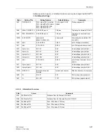
Setting of the Parameters for this Function
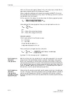
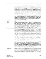
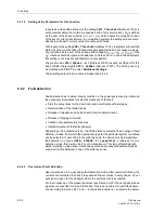
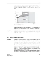
In systems with earthed star-point, the setting
3I0> Threshold
(Address
1203
) is
set somewhat below the minimum expected earth short-circuit current. 3
I
0
is defined
as the sum of the phase currents |
I
L1
+
I
L2
+
I
L3
|, which equals the star-point current
of the set of current transformers. In non-earthed systems the setting value is some-
what below the earth current value for double earth faults.
With regard to the setting
3U0> Threshold
(Address
1204
), in systems with earthed
starpoint, care must be taken that operational unsymmetries do not cause a pick-up.
3U
0
is defined as the sum of the phase-earth voltages |U
L1–E
+ U
L2–E
+ U
L3–E
|. If the
U
0
–criterion should be ignored, the address
1204
is set to
∞
. In non-earthed systems
this setting is not relevant and therefore not accessible.
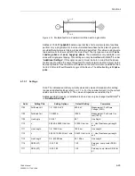
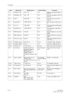
The preset value
3I0>/Iphmax
=
0.1
(Address
1207A
) usually is sufficient for the
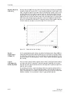
slope of
3I0
–characteristic
3I0>/ Iphmax
(Address
1207A
). This setting can only
be modified with DIGSI
®
4 under “Additional Settings”.
These settings are listed in a table in Subsection 6.2.2.4.
6.2.2
Fault detection
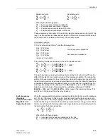
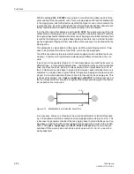
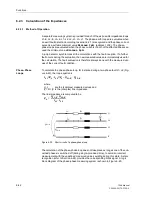
Fault detection has to detect a faulty condition in the power system and to initiate all
the necessary procedures for selective clearance of the fault:
•
Start the delay times for the directional and non-directional final stages
•
Determination of the faulted loops
•
Release of impedance calculation and direction determination
•
Release of tripping command
•
Initiation of supplementary functions
•
Indication/output of the faulty phase(s)
Depending on the ordered version, the 7SA6 distance protection has a range of fault
detection modes, from which the appropriate type for the particular system conditions
can be selected. If, according to the ordering code, the device only has impedance
fault detection, or if you set
DIS. PICKUP
=
Z< (quadrilat.)
(address
114
) as
detection mode, this Section 6.2.2 is of no importance. This type of fault detection
works implicitly, i.e the above-mentioned operations are executed automatically as
soon as a fault is detected in one of the distance zones.
6.2.2.1
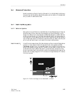
Overcurrent Fault Detection
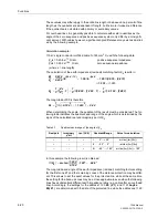
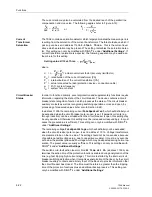
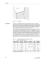
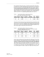
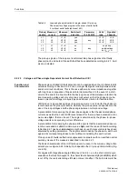
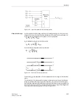
Overcurrent pick-up is a per phase fault detection mode. After numerical filtering, the
currents are monitored to check if they exceed the set values in every phase. An out-
put signal is given for the phase(s) where the set threshold is exceeded.
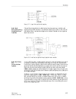
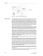
For the processing of the measured values (see Section 6.2.3) the per phase pick-up
signals are converted into loop information. This is done subject to earth-fault detec-
tion according to Section 6.2.1 and — in the earthed network — subject to the param-
Summary of Contents for siprotec 7SA6
Page 2: ...Siemens Aktiengesellschaft Book No C53000 G1176 C156 2 ...
Page 18: ...xviii 7SA6 Manual C53000 G1176 C156 2 ...
Page 32: ...Introduction 1 14 7SA6 Manual C53000 G1176 C156 2 ...
Page 82: ...Hardware and Connections 2 50 7SA6 Manual C53000 G1176 C156 2 ...
Page 119: ...SIPROTEC 4 Devices 4 25 7SA6 Manual C53000 G1176 C156 2 Figure 4 20 CFC Logic example ...
Page 190: ...Configuration 5 62 7SA6 Manual C53000 G1176 C156 2 ...
Page 652: ...Installation and Commissioning 8 78 7SA6 Manual C53000 G1176 C156 2 ...
Page 724: ...Technical Data 10 56 7SA6 Manual C53000 G1176 C156 ...
Page 800: ...Appendix A 76 7SA6 Manual C53000 G1176 C156 2 ...
Page 866: ...Appendix B 66 7SA6 Manual C53000 G1176 C156 2 ...

