SIPROTEC
®
4 Devices
4-7
7SA6 Manual
C53000-G1176-C156-2
4.2.2
DIGSI
®
4 Tool
DIGSI
®
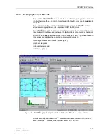
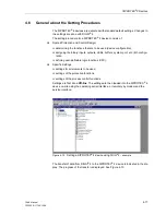
4 uses the familiar Windows operating environment.
User Guide
In DIGSI
®
4 only the settings that are available within a specific device are shown in
the specific windows. If a protective feature is changed from disabled to enabled in the
Device Configuration, then the settings relevant to that feature become available.
Entering settings for SIPROTEC
®
4 devices is easy due to many types of assistance
offered, such as context menus, pop-up lists for the selection of available options, and
specific limits for the entry of numerical values.
Configuring
Inputs and Outputs
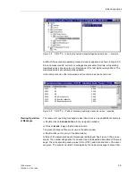
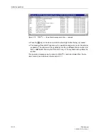
A configuration matrix is used to assign the binary inputs, output relays, and LEDs. In-
formation to be stored in the various buffers and transmitted via the system interface
is also selected in this matrix. The setting options are presented in an easy-to-read
tabular format. Parts of the matrix can be minimized or expanded as desired to simplify
the displayed sections, and therefore the setting process. Filter functions can reduce
the size of the matrix to display only relevant information.
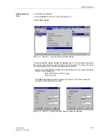
Passwords
Password entry is required for tasks such as changing settings, executing control
commands, or exercising the test and diagnostics features. The passwords protect
against unauthorized access to these critical tasks.
Commissioning
Aids
DIGSI
®
4 simplifies commissioning with test functions for the binary inputs, outputs
and LEDs. Control of primary equipment can be done. The measured values of the
device can be viewed with the program. Oscillographic fault records can be triggered
with DIGSI
®
4.
Help System
The help system clarifies the individual functions and settings, and provides additional
support.
Note:
Detailed information about DIGSI
®
4 can be found in the DIGSI
®
4 Manual, order
number E50417-H1176-C097.
Summary of Contents for siprotec 7SA6
Page 2: ...Siemens Aktiengesellschaft Book No C53000 G1176 C156 2 ...
Page 18: ...xviii 7SA6 Manual C53000 G1176 C156 2 ...
Page 32: ...Introduction 1 14 7SA6 Manual C53000 G1176 C156 2 ...
Page 82: ...Hardware and Connections 2 50 7SA6 Manual C53000 G1176 C156 2 ...
Page 119: ...SIPROTEC 4 Devices 4 25 7SA6 Manual C53000 G1176 C156 2 Figure 4 20 CFC Logic example ...
Page 190: ...Configuration 5 62 7SA6 Manual C53000 G1176 C156 2 ...
Page 652: ...Installation and Commissioning 8 78 7SA6 Manual C53000 G1176 C156 2 ...
Page 724: ...Technical Data 10 56 7SA6 Manual C53000 G1176 C156 ...
Page 800: ...Appendix A 76 7SA6 Manual C53000 G1176 C156 2 ...
Page 866: ...Appendix B 66 7SA6 Manual C53000 G1176 C156 2 ...

