Installation and Commissioning
8-8
7SA6 Manual
C53000-G1176-C156-2
Mounting with
Detached Operator
Panel
For mounting the device proceed as follows:
G
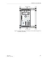
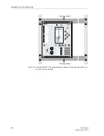
Fasten device of housing size
1
/
2
with 6 screws and device of housing size
1
/
1
with
10 screws. For dimensions see Section 10.22 (Figure 10-14 and 10-15).
G
Connect the ground on the rear plate of the device to the protective ground of the
panel. Using at least one M4 screw. The cross-sectional area of the ground wire
must be equal to the cross-sectional area of any other control conductor connected
to the device. The cross-section of the ground wire must be at least 2.5 mm
2
.
G
Connections are realized via the plug terminals or screw terminals on the rear side
of the device according to the circuit diagram.
When using forked lugs for direct connections or screw terminal, the screws, before
having inserted the lugs and wires, must be tightened in such a way that the screw
heads are even with the terminal block.
A ring lug must be centred in the connection chamber, in such a way that the screw
thread fits in the hole of the lug. Section 2.3 has pertinent information regarding wire
size, lugs, bending radii, etc.
G
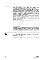
For mounting the detached operator panel please observe the following:
G
The removal of the 4 covers located at the corners of the front cover reveal 4 elon-
gated holes in the mounting bracket.
G
Insert the operator panel into the panel cut-out and fasten with four screws. For di-
mensions refer to Figure 10-16 in Section 10.22.
G
Mount the four covers.
G
Connect the ground on the rear plate of the operator control element to the protec-
tive ground of the panel using at least one M4 screw. The cross-sectional area of
the ground wire must be equal to the cross-sectional area of any other control con-
ductor connected to the device. The cross-section of the ground wire must be at
least 2.5 mm
2
.
G
Connect the operator panel to the device. Furthermore, plug the 68-pin connector
of the cable belonging to the operator panel into the corresponding connection at
the rear side of the device (see Section 2.3, Figure 2-33 and 2-34).
Caution!
Do never pull or plug the connector between the device and the detached operator
panel while the device is alive!
Summary of Contents for siprotec 7SA6
Page 2: ...Siemens Aktiengesellschaft Book No C53000 G1176 C156 2 ...
Page 18: ...xviii 7SA6 Manual C53000 G1176 C156 2 ...
Page 32: ...Introduction 1 14 7SA6 Manual C53000 G1176 C156 2 ...
Page 82: ...Hardware and Connections 2 50 7SA6 Manual C53000 G1176 C156 2 ...
Page 119: ...SIPROTEC 4 Devices 4 25 7SA6 Manual C53000 G1176 C156 2 Figure 4 20 CFC Logic example ...
Page 190: ...Configuration 5 62 7SA6 Manual C53000 G1176 C156 2 ...
Page 652: ...Installation and Commissioning 8 78 7SA6 Manual C53000 G1176 C156 2 ...
Page 724: ...Technical Data 10 56 7SA6 Manual C53000 G1176 C156 ...
Page 800: ...Appendix A 76 7SA6 Manual C53000 G1176 C156 2 ...
Page 866: ...Appendix B 66 7SA6 Manual C53000 G1176 C156 2 ...

