SIPROTEC
®
4 Devices
4-15
7SA6 Manual
C53000-G1176-C156-2
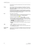
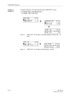
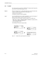
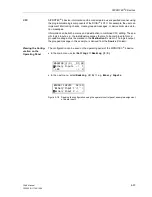
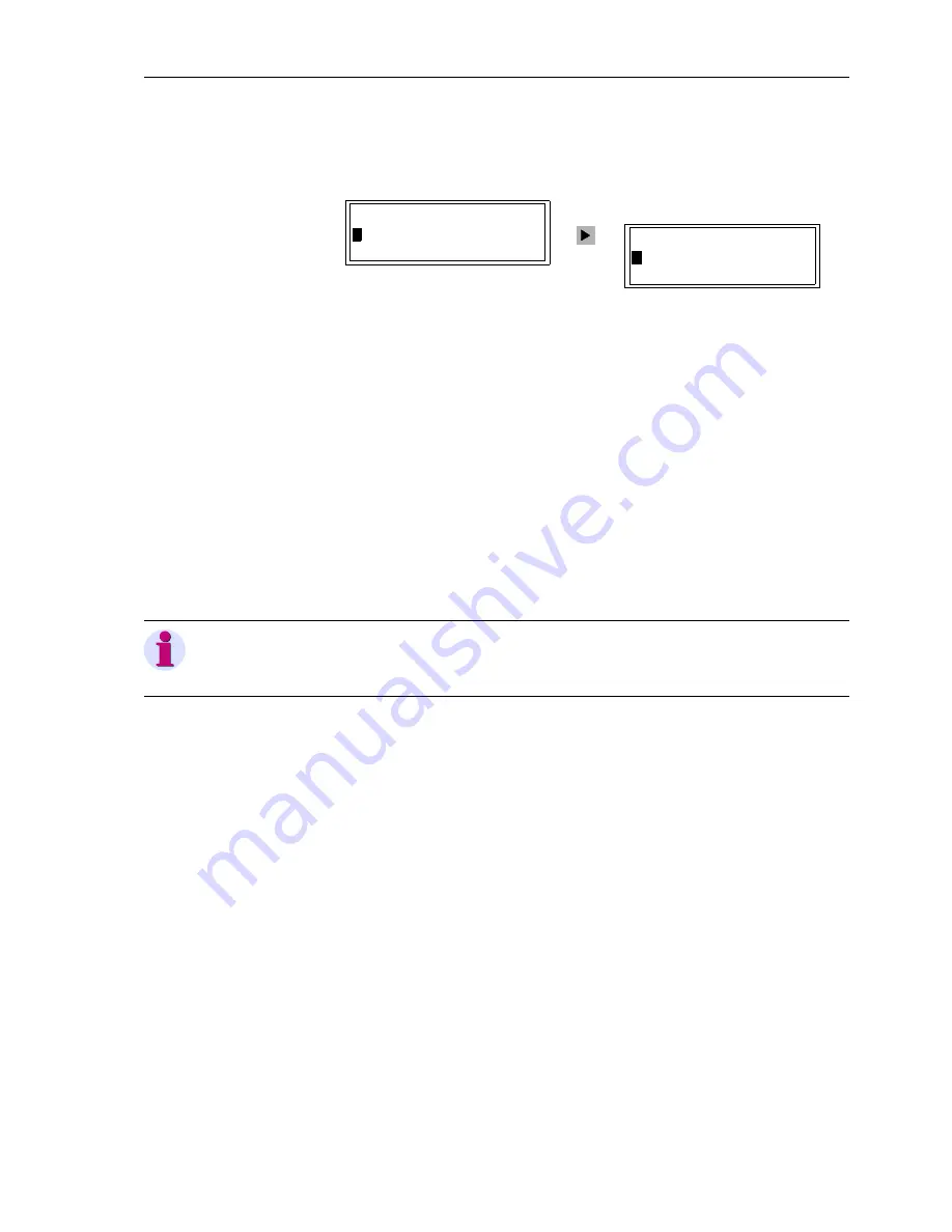
The status of a primary switch can be read out on the display using
BREAKER/SWITCH
→
Display
(Figure 4-10).
Figure 4-10
Determining primary switch status using the operator control panel
DIGSI
®
4
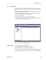
Control operations can be carried out using the DIGSI
®
4 Tool. Connect a PC to the
operating interface of the device on site, or communicate with the SIPROTEC
®
device
using a modem and the service interface.
DIGSI
®
4 must operate in the Online mode for this function.
•
Select
Control
in the Navigation window and double click on
Breaker /
Switches
in the data window.
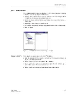
In the dialogue window that follows, all relevant primary switching equipment is dis-
played in a table with the present status.
•
Enter the intended switching direction in the Scheduled column. Answer the ques-
tion with
Yes
.
The password is requested, the interlocking conditions are checked, and the com-
mand is issued.
CFC
Using the graphically supported design tool CFC for logic functions in DIGSI
®
4, infor-
mation can be logically combined. Command outputs can be derived from the output
of logic functions. The link of the output of the CFC functions to the respective device
outputs is determined in the configuration matrix.
Passwords
Only authorized personnel can perform switching operations. Switching operations
are protected by passwords.
Interlocking
Command outputs may be subject to interlocking checks, which can be configured in-
dividually and graphically using the CFC logic too. Standard interlocking, such as
ground switch closed status indication, may be already contained in the basic settings
of certain device types when delivered from the factory.
Command Process-
ing Times
Details about the command output time, checkback indication monitoring time, etc.,
are entered within the framework of the settings.
Event Recording
All switching operations are recorded in the message list with date and time.
DISPLAY 01/03
--------------------
>
52Breaker OPEN
Disc.Swit. CLOS
BREAKER/SWITCH 01/04
---------------------
>
Display –> 1
>
Control –> 2
Note:
The control option of DIGSI
®
4 is typically used during commissioning, and for test and
diagnostic purposes.
Summary of Contents for siprotec 7SA6
Page 2: ...Siemens Aktiengesellschaft Book No C53000 G1176 C156 2 ...
Page 18: ...xviii 7SA6 Manual C53000 G1176 C156 2 ...
Page 32: ...Introduction 1 14 7SA6 Manual C53000 G1176 C156 2 ...
Page 82: ...Hardware and Connections 2 50 7SA6 Manual C53000 G1176 C156 2 ...
Page 119: ...SIPROTEC 4 Devices 4 25 7SA6 Manual C53000 G1176 C156 2 Figure 4 20 CFC Logic example ...
Page 190: ...Configuration 5 62 7SA6 Manual C53000 G1176 C156 2 ...
Page 652: ...Installation and Commissioning 8 78 7SA6 Manual C53000 G1176 C156 2 ...
Page 724: ...Technical Data 10 56 7SA6 Manual C53000 G1176 C156 ...
Page 800: ...Appendix A 76 7SA6 Manual C53000 G1176 C156 2 ...
Page 866: ...Appendix B 66 7SA6 Manual C53000 G1176 C156 2 ...


