Functions
6-191
7SA6 Manual
C53000-G1176-C156-2
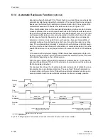
be the first cycle that is executed) it is possible to determine which reclose cycles are
executed depending on the time used by the protection function to trip.
Example 1: 3 cycles are set. At least the first cycle is configured to start the recloser
(allowed to be the first cycle that is carried out). The action times are set as follows:
1.AR: T-ACTION
= 0.2 s;
2.AR: T-ACTION
= 0.8 s;
3.AR: T-ACTION
= 1.2 s;
Since reclosure is ready before the fault occurs, the first trip following a fault is fast,
i.e. before the expiry of any action time. The automatic reclosure function is therefore
started (the first cycle is initiated). After an unsuccessful reclosure attempt the 2nd
cycle would usually be initiated; but in this case the time-overcurrent protection trips
according to its set grading time after 1 s. Since the action time for the second cycle
was exceeded in this case, it is not initiated. The 3rd cycle according to its parameters
is therefore now initiated. If the trip command only appeared more than 1.2 s after the
1st reclosure, there would have been no further reclosure.
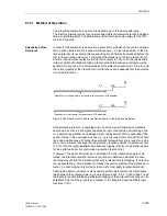
Example 2: 3 cycles are set. Starting is only allowed for the first. The action times are
set as in example 1.
The first protection trip takes place 0.5 s after starting. Since the action time for the 1st
cycle has already expired at this time, this cycle cannot start the automatic reclosure
function. As the 2nd and 3rd cycles are not permitted to start the reclose function they
will also not be initiated. Therefore no reclosure takes place as no starting took place.
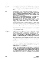
Example 3: 3 cycles are set. At least the first two cycles are set such that they can start
the recloser. The action times are set as in example 1.
The first protection trip takes place 0.5 s after starting. Since the action time for the 1st
cycle has already expired at this time, this cycle cannot start the automatic reclosure
circuit. However the 2nd cycle, which is also able to start the recloser, is activated im-
mediately. This 2nd cycle therefore starts the automatic reclosure circuit, the 1st cycle
is practically skipped.
Operating Modes of
the Automatic
Reclosure Function
The dead times — in other words, the time from fault clearance (reset of the trip com-
mand or indication by auxiliary contacts) upto the initiation of the automatic reclose
command — may vary, depending on the automatic reclosure function operating
mode selected when setting the scope of functions (section 5.1) and on the resulting
signals generated by the protective functions selected to initiate reclosing.
In the
Target on TRIP
operating mode single-pole or single/three-pole reclose cy-
cles are possible if the device and the circuit-breaker are suitable. In this case different
dead times after single-pole tripping on the one hand and after three-pole tripping on
the other hand are possible (for every reclose cycle). The protective function that is-
sues the trip command determines the type of trip: single-pole or three-pole. Selection
of the dead time depends on this.
In the
with PICKUP
operating mode, different dead times can be set for every
reclose cycle after single-, two- and three-phase faults. Selection of the dead time in
this case depends on the type of fault determined by the initiating protection function
at the instant that the trip commands reset. This operating mode allows the dead times
to be dependent on the type of fault in the case of three-pole reclose cycles.
Reclose Block
Different conditions lead to blocking of the automatic reclosure. No reclosure is for ex-
ample possible if it is blocked via a binary input. If the automatic reclosure has not yet
been started, it cannot be started at all. If a reclose cycle is already in progress, dy-
namic blocking takes place (see below).
Each individual cycle may also be blocked via binary input. In this case the cycle con-
cerned is declared as invalid and will be skipped in the sequence of permissible
Summary of Contents for siprotec 7SA6
Page 2: ...Siemens Aktiengesellschaft Book No C53000 G1176 C156 2 ...
Page 18: ...xviii 7SA6 Manual C53000 G1176 C156 2 ...
Page 32: ...Introduction 1 14 7SA6 Manual C53000 G1176 C156 2 ...
Page 82: ...Hardware and Connections 2 50 7SA6 Manual C53000 G1176 C156 2 ...
Page 119: ...SIPROTEC 4 Devices 4 25 7SA6 Manual C53000 G1176 C156 2 Figure 4 20 CFC Logic example ...
Page 190: ...Configuration 5 62 7SA6 Manual C53000 G1176 C156 2 ...
Page 652: ...Installation and Commissioning 8 78 7SA6 Manual C53000 G1176 C156 2 ...
Page 724: ...Technical Data 10 56 7SA6 Manual C53000 G1176 C156 ...
Page 800: ...Appendix A 76 7SA6 Manual C53000 G1176 C156 2 ...
Page 866: ...Appendix B 66 7SA6 Manual C53000 G1176 C156 2 ...

