Functions
6-95
7SA6 Manual
C53000-G1176-C156-2
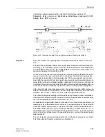
On two terminal lines, the signal transmission may be done phase segregated. On
three terminal lines, the transmit signal is sent to both opposite line ends. The receive
signals are then combined with an OR logic function. By means of the parameter
Line
Config.
(address
2102
) the device is informed whether it has one or two opposite
ends. If digital protection transmission is applied and the protection data interface is
used, signals will always be transmitted phase-selectively.
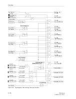
During disturbance of the signal transmission path, the overreaching zone Z1B may
be activated by an automatic reclosure via the binary input “
>Enable ARzones
” and
address
1357
“
1st AR -> Z1B
” set to “Yes” (refer also to Figure 6-38 bottom).
If at one line end there is weak or zero infeed, so that the distance protection does not
pick up, the circuit breaker can still be tripped. This “weak-infeed tripping” is referred
to in Section 6.9.
6.6.1.3
Direct Underreach Transfer Trip
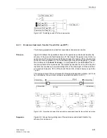
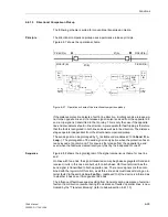
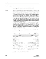
The following scheme is suited for conventional transmission media.
Principle
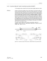
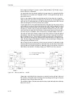
As is the case with permissive transfer trip via pick-up or zone acceleration, a fault in
the first zone Z1 is transmitted to the opposite line end by means of a transfer trip sig-
nal. The signal received there causes a trip without further queries after a short secu-
rity margin T
v
(settable under address
2202
Trip Time DELAY
) (Figure 6-54). The
transmit signal can be prolonged by T
S
(settable under address
2103A
Send Pro-
long.
), to compensate for possible differences in the pick-up time at the two line
ends. The distance protection is set such that the first zone reaches up to approxi-
mately 80 % of the line length. On three terminal lines Z1 is also set to approximately
80 % of the shorter line section, but at least beyond the tee off point. The overreaching
zone Z1B is not required here. It may however be activated by internal automatic re-
closure or external criteria via the binary input “
>Enable ARzones
” (refer also to Fig-
ure 6-38 bottom).
The advantage compared to the other permissive underreach transfer trip schemes
lies in the fact that both line ends are tripped without the necessity for any further
measures, even if one line end has no infeed. There is however no further supervision
of the trip signal at the receiving end.
The direct underreach transfer trip application is not provided by its own selectable tel-
eprotection scheme setting, but implemented by setting the teleprotection supplement
to operate in one of the permissive underreach transfer trip schemes (address
121
Teleprot. Dist.
=
PUTT
or
PUTT with pick-up
), and using the binary inputs
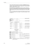
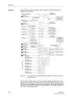
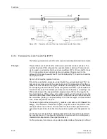
for direct external trip at the receiving end. Accordingly, the transmit circuit in Subsec-
tion 6.6.1.1 (Figure 6-51) or 6.6.1.2 (Figure 6-53) applies. For the receive circuit the
logic of the “external trip” as described in Section 6.10 applies.
On two terminal lines, the transmission can be phase segregated. On three terminal
lines the transmit signal is sent to both opposite line ends. The receive signals are then
combined with a logical OR function.
Summary of Contents for siprotec 7SA6
Page 2: ...Siemens Aktiengesellschaft Book No C53000 G1176 C156 2 ...
Page 18: ...xviii 7SA6 Manual C53000 G1176 C156 2 ...
Page 32: ...Introduction 1 14 7SA6 Manual C53000 G1176 C156 2 ...
Page 82: ...Hardware and Connections 2 50 7SA6 Manual C53000 G1176 C156 2 ...
Page 119: ...SIPROTEC 4 Devices 4 25 7SA6 Manual C53000 G1176 C156 2 Figure 4 20 CFC Logic example ...
Page 190: ...Configuration 5 62 7SA6 Manual C53000 G1176 C156 2 ...
Page 652: ...Installation and Commissioning 8 78 7SA6 Manual C53000 G1176 C156 2 ...
Page 724: ...Technical Data 10 56 7SA6 Manual C53000 G1176 C156 ...
Page 800: ...Appendix A 76 7SA6 Manual C53000 G1176 C156 2 ...
Page 866: ...Appendix B 66 7SA6 Manual C53000 G1176 C156 2 ...


