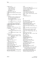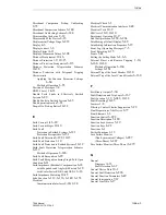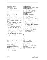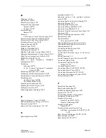
Index
Index-3
7SA6 Manual
C53000-G1176-C156-2
Directional
Comparison
Pickup,
Unblocking
8-72
Directional Comparison Scheme
6-140
Directional Unblocking Scheme
6-144
Disassembling the device
9-12
Disassembly of the Device
8-16
Displacement Voltage Stage
6-235
Display
4-6
Display contrast
3-6
Display Editor
A-11
Display of Measured Values
6-308
Distance Measurement
10-16
Distance Protection
1-9, 10-15
Distance Protection Prerequisites
6-115
Distance
Protection
Teleprotection
Schemes
10-18
Distance Protection with Polygonal Tripping
Characteristic
Applying the Function Parameter Settings
6-60
Method of Operation
6-55
Division of Messages
7-4
DNP3.0 Level 2
4-31
Double Earth Faults in Effectively Earthed
Systems
6-49
Double Faults in Earthed Systems
6-45
Double point indication
5-21
Drop-off to Pick-up Ratios
10-32
E
Earth Current 3 I0
6-29
Earth Current Stages
10-19
Earth Fault
Protection in Earthed Systems
6-121
Protection Prerequisites
6-151
Earth Fault Detection
6-182, 10-15
Earth Fault Protection
1-10
Earth Fault Protection in Earthed Systems
10-19
Earth Fault Protection Teleprotection Schemes
6-139
Method of Operation
6-140
Earth Fault Recognition
6-29
Earth Fault Recognition during Single-Pole Open
Condition
6-31
Earth Impedance (Residual) Compensation
6-18
with Magnitude and Angle (K0-Factor)
6-19
with Scalar Factor RE/RL and XE/XL
6-18
Earth Impedance Matching
10-15
Echo Function
6-112, 6-116, 6-149, 6-153
Electrical
Communication Interfaces
2-20, 2-34
Electrical Check
3-3
Electrical Communication Interfaces
2-48
Electrical Tests
10-9
EMC tests
10-9, 10-10
Emergency Operation
10-17
End fault protection
6-258, 6-262
Establishing a Default Display
5-48
Establishing Information Properties
5-19
Event Log (Operating Messages)
7-5
Event Recording
4-15
Events
5-43
Exiting the Setting Mode
6-4, 6-6
External Direct and Remote Tripping
1-10,
6-160, 10-30
Method of Operation
6-160
Settings
6-161
External Trip of the Local Breaker
10-30
External Trip of the Local Circuit Breaker
6-160
F
Fast Binary Outputs
5-30
Fault Detection and Trip Logic
6-167
Fault Location
1-12, 6-242, 10-38
Fault Recording
10-45
Features
1-8
Filtering / Contact Chatter Suppression
5-22
Final Preparation of the Device
8-77
Front Elements
1-3
Function Control
6-292
Function Description
6-189
Function key as source
5-29
Function Keys
4-22
Functions
6-1
Further Functions
1-13
Fuse Failure Monitor
(Non-Symmetrical Voltages)
6-287
(Three-Phase)
6-287
Fuse Failure Monitor (Three-Phase)
6-279
G
General
Diagrams
A-13
Fault Detection
6-67
General Device Data
10-2
General Fault Detection
6-296
General Function Parameters
6-49
General Interrogation
7-12
General Line Data
6-17
Summary of Contents for siprotec 7SA6
Page 2: ...Siemens Aktiengesellschaft Book No C53000 G1176 C156 2 ...
Page 18: ...xviii 7SA6 Manual C53000 G1176 C156 2 ...
Page 32: ...Introduction 1 14 7SA6 Manual C53000 G1176 C156 2 ...
Page 82: ...Hardware and Connections 2 50 7SA6 Manual C53000 G1176 C156 2 ...
Page 119: ...SIPROTEC 4 Devices 4 25 7SA6 Manual C53000 G1176 C156 2 Figure 4 20 CFC Logic example ...
Page 190: ...Configuration 5 62 7SA6 Manual C53000 G1176 C156 2 ...
Page 652: ...Installation and Commissioning 8 78 7SA6 Manual C53000 G1176 C156 2 ...
Page 724: ...Technical Data 10 56 7SA6 Manual C53000 G1176 C156 ...
Page 800: ...Appendix A 76 7SA6 Manual C53000 G1176 C156 2 ...
Page 866: ...Appendix B 66 7SA6 Manual C53000 G1176 C156 2 ...

