Functions
6-23
7SA6 Manual
C53000-G1176-C156-2
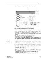
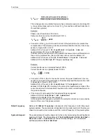
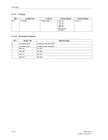
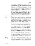
In address
1134
Line Closure
the criteria for the internal recognition of line ener-
gization are determined. In the case of
only with ManCl
only the manual close sig-
nal derived via binary input is used to recognize the circuit breaker closing condition.
With the setting
I OR U or ManCl
the measured currents or voltages are used as
an additional criterion to recognise energization of the line.
CB OR I or M/C
on the
other hand implies that either the currents or the circuit breaker auxiliary contact state
is used to determine closing of the circuit breaker. If the voltage transformers are not
situated on the line side, the setting
CB OR I or M/C
must be used. In the case of
I or Man.Close
only the currents or the manual close signals are used to recognize
closing of the circuit breaker.
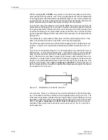
While the seal-in time after all closures (
SI Time all Cl.
address
1132A
, refer
above) is activated following each recognition of line energization, the seal-in time af-
ter manual closures (
SI Time Man.Cl
address
1150A
) is the time following manual
closure during which special influence of the protection functions is activated (e.g. in-
creased reach of the distance protection). This setting can only be modified with
DIGSI
®
4 under “Additional Settings”.
In address
1151
SYN.MAN.CL
the selection is made whether the synchronism check
between the busbar voltage and the voltage of the switched feeder must be done for
a manual close. To do this, either the device must have integrated synchronism check
function or an external device for synchronism check must be connected.
In the former case the synchronism check function must be configured (Section 5.1)
as available, a busbar voltage must be connected to the device and this must be cor-
rectly parameterized in the system data (Section 6.1.1, address
210
U4 transform-
er
=
Usync transf.
as well as the corresponding factors).
If no synchronism check is to be performed with manual closing, set
SYN.MAN.CL
=
without Synchronism-check
. If on the other hand synchronism check is re-
quired, set
with Synchronism-check.
If the manual close function of the device is
not to be used at all, set
SYN.MAN.CL
to
No
.
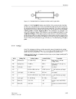
Address
1135
Reset Trip CMD
determines which criteria allow for the reset of an
issued trip command. The setting
CurrentOpenPole
ensures that the trip command
resets after the current disappears. The measured current must drop below the value
set in address
1130A
PoleOpenCurrent
before the trip command resets (see
above). With the setting
Current AND CB
the circuit breaker auxiliary contact must
additionally indicate that the circuit breaker has opened. This setting demands that the
status of the auxiliary contacts is marshalled to a binary input.
Three-pole
Coupling
Address
1155
3pole coupling
determines whether each trip command resulting
from pickup in more than one phase is three-pole, or if three-pole coupling of the trip
command only results when more than one phase is tripped. This setting is only rele-
vant with one- and three-pole tripping and therefore only available in this version. Ad-
ditional information can be found in Section 6.22.3 fault detection logic of the device.
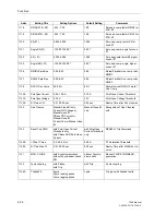
Note:
For CB Test and automatic reclosure the CB auxiliary contact status derived with the
binary inputs > CB1 ... (FNo. 366 - 371, 410 and 411) are relevant for indicating the
CB switching status. The other binary inputs > CB ... (FNo. 351 - 353, 379 and 380)
apply to the recognition of line status (address 1134) and reset of trip command
(address 1135) which is used by the other protection functions, e.g. echo function,
switch-onto-fault overcurrent etc. For applications with only one CB, both binary input
functions e.g. 366 and 351 can be allocated to the same physical input.
Summary of Contents for siprotec 7SA6
Page 2: ...Siemens Aktiengesellschaft Book No C53000 G1176 C156 2 ...
Page 18: ...xviii 7SA6 Manual C53000 G1176 C156 2 ...
Page 32: ...Introduction 1 14 7SA6 Manual C53000 G1176 C156 2 ...
Page 82: ...Hardware and Connections 2 50 7SA6 Manual C53000 G1176 C156 2 ...
Page 119: ...SIPROTEC 4 Devices 4 25 7SA6 Manual C53000 G1176 C156 2 Figure 4 20 CFC Logic example ...
Page 190: ...Configuration 5 62 7SA6 Manual C53000 G1176 C156 2 ...
Page 652: ...Installation and Commissioning 8 78 7SA6 Manual C53000 G1176 C156 2 ...
Page 724: ...Technical Data 10 56 7SA6 Manual C53000 G1176 C156 ...
Page 800: ...Appendix A 76 7SA6 Manual C53000 G1176 C156 2 ...
Page 866: ...Appendix B 66 7SA6 Manual C53000 G1176 C156 2 ...

