Installation and Commissioning
8-36
7SA6 Manual
C53000-G1176-C156-2
8.1.3.4
Interface Modules
Replacing
Interface Modules
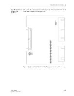
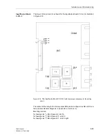
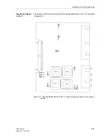
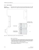
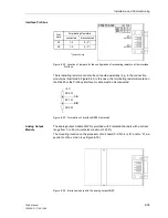
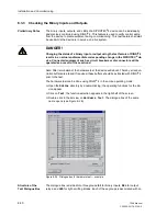
The interface modules are located on the processor printed circuit board C–CPU–2 (
in Figure 8-9 to 8-11). Figure 8-19 shows the printed circuit board and the modules.
Figure 8-19
Processor printed circuit board C–CPU–2 with interface modules
Please note the following:
G
Only interface modules of devices with panel flush mounting and cubicle mounting
as well as of mounting devices with detached operator panel can be exchanged. In-
terface modules of devices in surface mounting housings with double-level termi-
nals must be exchanged in our manufacturing centre.
G
Use only interface modules that can be ordered in our facilities
(see also Appendix A, Section A.1.1).
B
D
Mounting Location
(Rear Side of Housing)
Analog Output
System Interface
or Analog Output
Summary of Contents for siprotec 7SA6
Page 2: ...Siemens Aktiengesellschaft Book No C53000 G1176 C156 2 ...
Page 18: ...xviii 7SA6 Manual C53000 G1176 C156 2 ...
Page 32: ...Introduction 1 14 7SA6 Manual C53000 G1176 C156 2 ...
Page 82: ...Hardware and Connections 2 50 7SA6 Manual C53000 G1176 C156 2 ...
Page 119: ...SIPROTEC 4 Devices 4 25 7SA6 Manual C53000 G1176 C156 2 Figure 4 20 CFC Logic example ...
Page 190: ...Configuration 5 62 7SA6 Manual C53000 G1176 C156 2 ...
Page 652: ...Installation and Commissioning 8 78 7SA6 Manual C53000 G1176 C156 2 ...
Page 724: ...Technical Data 10 56 7SA6 Manual C53000 G1176 C156 ...
Page 800: ...Appendix A 76 7SA6 Manual C53000 G1176 C156 2 ...
Page 866: ...Appendix B 66 7SA6 Manual C53000 G1176 C156 2 ...

