Functions
6-113
7SA6 Manual
C53000-G1176-C156-2
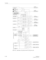
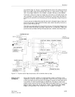
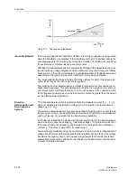
If there is no fault detection, the echo function causes the received signal to be sent
back to the other line end as an “echo”, where it is used to initiate permissive tripping.
The detection of the weak infeed and accordingly the requirement for an echo are
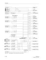
combined in the central AND gate (Figure 6-67). The distance protection must neither
be switched off nor blocked, as it would otherwise always produce an echo due to the
missing fault detection. If however the time delayed overcurrent protection is used as
an emergency function, an echo is nevertheless possible if the distance protection is
out of service, because the fault detection of the emergency overcurrent protection re-
places the distance protection fault detection. During this mode of operation, the emer-
gency overcurrent protection must naturally not also be blocked or switched off.
The essential condition for an echo is the absence of distance protection or overcur-
rent protection fault detection with the simultaneous reception of a signal from the tel-
eprotection scheme logic, as shown in the corresponding logic diagrams (Figure 6-56
or 6-60).
To avoid an incorrect echo following switching off of the line and reset of the fault de-
tection, the RS flip-flop in Figure 6-67 latches the fault detection condition until the sig-
nal receive condition resets, thereby barring the release of an echo. The echo can in
any event be blocked via the binary input „
>Dis.T.BlkEcho
“.
If the conditions for an echo signal are met, a short delay
Trip/Echo DELAY
is ini-
tially activated. This delay is necessary to avoid transmission of the echo if the protec-
tion at the weak line end has a longer fault detection time during reverse faults or if it
picks up a little later due to unfavourable fault current distribution. If however the circuit
breaker at the non-feeding line end is open, this delay of the echo signal is not re-
quired. The echo delay time may then be bypassed. The circuit breaker switching
state is provided by the central information control functions. (refer to Subsection
6.22.2).
The echo impulse is then issued (event output “
ECHO SIGNAL
”). It’s length is set with
the parameter
Trip EXTENSION
.
After issue of the echo impulse, the transmission of a new echo is prevented for at
least 20 ms. This prevents the repetition of an echo after the line has been switched
off.
In the case of the blocking scheme and the underreach transfer trip scheme, the echo
function is not required and therefore ineffective.
Note:
The “
ECHO SIGNAL
” (F.No. 4246) must be separately assigned to the output relay(s)
for signal transmission, as it is not contained in the transmit signals “
Dis.T.SEND
” or
“
Dis.T.SEND L*
”.
Summary of Contents for siprotec 7SA6
Page 2: ...Siemens Aktiengesellschaft Book No C53000 G1176 C156 2 ...
Page 18: ...xviii 7SA6 Manual C53000 G1176 C156 2 ...
Page 32: ...Introduction 1 14 7SA6 Manual C53000 G1176 C156 2 ...
Page 82: ...Hardware and Connections 2 50 7SA6 Manual C53000 G1176 C156 2 ...
Page 119: ...SIPROTEC 4 Devices 4 25 7SA6 Manual C53000 G1176 C156 2 Figure 4 20 CFC Logic example ...
Page 190: ...Configuration 5 62 7SA6 Manual C53000 G1176 C156 2 ...
Page 652: ...Installation and Commissioning 8 78 7SA6 Manual C53000 G1176 C156 2 ...
Page 724: ...Technical Data 10 56 7SA6 Manual C53000 G1176 C156 ...
Page 800: ...Appendix A 76 7SA6 Manual C53000 G1176 C156 2 ...
Page 866: ...Appendix B 66 7SA6 Manual C53000 G1176 C156 2 ...

