Control During Operation
7-38
7SA6 Manual
C53000-G1176-C156-2
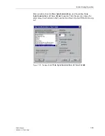
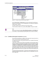
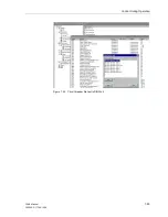
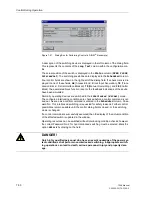
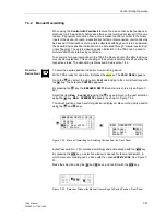
Figure 7-39
Example: Transfer Block Activated in DIGSI
®
4
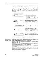
Click on
Block Data Transmission
to activate or deactivate the transfer block.
After entry of Password No. 4 for test and diagnostics, and confirmation with
OK
, the
setting change is complete.
Activation is indicated with a check mark in front of the command.
Follow the same procedure for the command
Test Mode
, if this option is desired.
7.2.4
Test Mode of the Signal Transmission (optional)
If a protection data interface is provided, the “local test mode” can be selected for re-
vision or commissioning of the teleprotection schemes.
This enables the operation of the signal transmission via the protection data interface
to be tested as follows:
A fault case is simulated in the local device generating the corresponding transmission
signals. The signals are transmitted to the opposite line end with the added message
“Test Mode”. The signals received at the opposite line end are mirrored, i.e. they are
sent back phase segregated from the opposite line end as own signals marked with
“Test Mode”. The local device receives these mirrored test signals and adds them to
its own teleprotection scheme which can use these signals to generate a trip signal if
necessary. No tripping occurs in the devices as the signals have the message “Test
Mode” attached to them and are thus recognized as not relevant for protection purpos-
es.
For mode changeover Password No. 2 is required (for switching/tagging/manual over-
writing). Every mode that has been changed is stored in the device safe from an aux-
iliary voltage failure.
Note:
Remember to change the settings for Block Data Transmission and Test Mode back
to the desired, in-service settings (both typically
OFF
) when the tests are complete.
Summary of Contents for siprotec 7SA6
Page 2: ...Siemens Aktiengesellschaft Book No C53000 G1176 C156 2 ...
Page 18: ...xviii 7SA6 Manual C53000 G1176 C156 2 ...
Page 32: ...Introduction 1 14 7SA6 Manual C53000 G1176 C156 2 ...
Page 82: ...Hardware and Connections 2 50 7SA6 Manual C53000 G1176 C156 2 ...
Page 119: ...SIPROTEC 4 Devices 4 25 7SA6 Manual C53000 G1176 C156 2 Figure 4 20 CFC Logic example ...
Page 190: ...Configuration 5 62 7SA6 Manual C53000 G1176 C156 2 ...
Page 652: ...Installation and Commissioning 8 78 7SA6 Manual C53000 G1176 C156 2 ...
Page 724: ...Technical Data 10 56 7SA6 Manual C53000 G1176 C156 ...
Page 800: ...Appendix A 76 7SA6 Manual C53000 G1176 C156 2 ...
Page 866: ...Appendix B 66 7SA6 Manual C53000 G1176 C156 2 ...

