Configuration
5-5
7SA6 Manual
C53000-G1176-C156-2
ferred to as “inverse” may also be used as a fourth definite time stage
Definite
Time
. Alternatively the earth fault protection function controlled by zero sequence
voltage
U0 inverse
can be selected. The various characteristics are shown in the
technical data. The earth fault protection may naturally also be disabled (
Disabled
).
If the device has an automatic reclosure, the addresses
133
and
134
are significant.
If no reclosure is desired at the feeder for which 7SA6 is used or only an external de-
vice is used for reclosure, address
133
AUTO RECLOSE
is switched to
Disabled
. Au-
tomatic reclosure is only permitted for overhead lines. It may not be used in any other
case. If the protected object consists of a combination of overhead lines and other
equipment (e.g. overhead line in a block with a transformer or overheadline/cable), re-
closure is only permissible if it can be ensured that it can only take place in the event
of a fault on the overhead line.
Otherwise set the number of desired reclosure attempts there. You can select
1 AR cycle
to
8 AR cycles
. You can also set
ADT
(adaptive dead time): in this
case the behavior of the automatic reclosure depends on the cycles of the remote end.
However, the number of cycles must be set at least at one end of the line and this end
must have a reliable infeed. The other end or ends may operate with adaptive dead
time. See section 6.14.1 for detailed explanations.
The
AR Control Mode
under address
134
allows a total of four options. You can
determine whether the sequence of automatic reclosure cycles is defined by the fault
situation of the pick-up of the starting protection function(s) (only for three-pole trip-
ping) or by the type of trip command. The automatic reclosure can also operate with
or without action time.
The
Trip with T-action
or
Trip without T-action
command setting is pre-
ferred when single-pole or single/three-pole automatic reclosure cycles are planned
and are possible. In this case different dead times (for every interrupt cycle) are pos-
sible after single-pole tripping and after three-pole tripping. The tripping protection
function determines the type of tripping: single-pole or three-pole. The dead time is
controlled dependent on this.
Using the
Pickup with T-action
or
Pickup without T-action
setting, dif-
ferent dead times can be set for the auto-reclosure cycles after single, two and three-
phase faults. The fault detection configuration of the protection functions at the time
the trip command disappears is decisive. This operating mode also enables the dead
times to be made dependent on the type of fault for three-pole interrupt cycles. Trip-
ping is always three-pole.
The
Trip with T-action
setting provides an action time for every interrupt cycle.
This is started by the general starting signal (i. e. logic OR combination of all internal
and external start signals of all protection functions which are configured to start the
automatic reclosure function. If there is still no trip command when the action time ex-
pired, the corresponding automatic reclosure cycle cannot be executed. See section
6.14.1 for further explanations. For the time graded protection this setting is recom-
mended. If the protection function to operate with reclosure does not have a general
fault detection signal for starting the action times, select the setting
Trip without
T-action
.
In address
138
Fault Locator
for fault location the user determines not only the
settings
Enabled
and
Disabled
, but also the function that the fault distance is di-
rected via binary outputs as BCD-Code (4 bit units, 4 bit tens, 1 Bit hundreds as well
as “Data valid” (
with BCD-output
). The required number of output relays (FNo
1153
to
1152)
must therefore be available and allocated.
For the trip circuit supervision the number of trip circuits that shall be monitored is set
in address
140
Trip Cir. Sup.
with the following settings:
1 Trip circuit
,
2
Trip circuits
or
3 Trip circuits
if they are required (Disabled).
Summary of Contents for siprotec 7SA6
Page 2: ...Siemens Aktiengesellschaft Book No C53000 G1176 C156 2 ...
Page 18: ...xviii 7SA6 Manual C53000 G1176 C156 2 ...
Page 32: ...Introduction 1 14 7SA6 Manual C53000 G1176 C156 2 ...
Page 82: ...Hardware and Connections 2 50 7SA6 Manual C53000 G1176 C156 2 ...
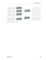
Page 119: ...SIPROTEC 4 Devices 4 25 7SA6 Manual C53000 G1176 C156 2 Figure 4 20 CFC Logic example ...
Page 190: ...Configuration 5 62 7SA6 Manual C53000 G1176 C156 2 ...
Page 652: ...Installation and Commissioning 8 78 7SA6 Manual C53000 G1176 C156 2 ...
Page 724: ...Technical Data 10 56 7SA6 Manual C53000 G1176 C156 ...
Page 800: ...Appendix A 76 7SA6 Manual C53000 G1176 C156 2 ...
Page 866: ...Appendix B 66 7SA6 Manual C53000 G1176 C156 2 ...

