Functions
6-236
7SA6 Manual
C53000-G1176-C156-2
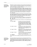
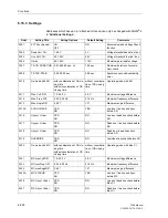
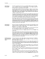
Undervoltage
Phase–Earth
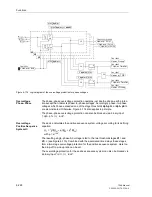
The phase undervoltage stages can be switched
On
or Off in address
3751
Uph-
e<(<)
. In addition to this, you can set
Alarm Only
, i.e. these stages operate and
send alarms but do not generate any trip commands.
This undervoltage protection function has two stages. The
Uph-e<
stage (address
3752
) operates with the longer set time value
T Uph-e<
(address
3753
) for a slight
undervoltages. However, it must not be set above the admissible undervoltage. In
case of severe voltage drops the
Uph-e<<
stage
(address
3754
) with a time delay
T Uph-e<<
(address
3755
) is active.
The setting of voltage and time values depends on the intended use, that is why gen-
eral setting recommendations cannot be given. With regard to load shedding, for ex-
ample, the values mostly depend on a priority grading schedule. If stability problems
occur, admissible undervoltages and their duration must be considered. With induc-
tion machines the undervoltages influence the admissible torque thresholds.
If the voltage transformers are located on the line side, the measuring voltages will be
missing if the line is disconnected. To avoid that the undervoltage stages in these cas-
es are or remain picked up, the current criterion
CURR.SUP. Uphe<
(address
3758
)
is switche
d
On
. With busbar side voltage transformers it can be switched
Off
. How-
ever, with a dead busbar the undervoltage protection picks up and expires, if it is not
blocked by other criteria or binary inputs.
Undervoltage
Phase–Phase
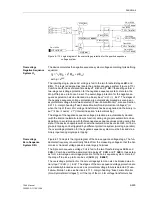
Basically, the same considerations apply as for the phase undervoltage stages. These
stages may replace the phase voltage stages or be used additionally. Address
3761
Uph-ph<(<)
is set to
On
,
Off
or
Alarm Only
.
As phase–to–phase voltages are monitored, the phase–to–phase values are used for
the settings
Uph-ph<
(address
3762
) and
Uph-ph<<
(address
3764
).
The corresponding times delay are
T Uph-ph<
(address
3763
) und
T Uphph<<
(ad-
dress
3765
).
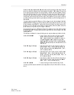
If the voltage transformers are located on the line side, the measuring voltages will
missing if the line is disconnected. To avoid that the undervoltage levels in these cases
are or remain picked up, the current criterion
CURR.SUP.Uphph<
(address
3768
) is
switche
d
On
. With busbar side voltage transformers it can be switched
Off
. Howev-
er, with a dead busbar the undervoltage protection picks up and expires, if it is not
blocked by other criteria via binary inputs.
Positive Sequence
System Undervolt-
age U
1
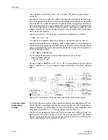
The positive sequence undervoltage stages can be used instead of or in addition to
previously mentioned undervoltage stages. The address
3771
U1<(<)
is set to
On
,
Off
or
Alarm Only
, accordingly.
Basically, the same considerations apply as for the other undervoltage stages. Espe-
cially in case of stability problems, the positive sequence system is advantageous,
since the positive sequence system is relevant for the limit of the stable energy trans-
mission in most applications.
To achieve the two-stage condition, the
U1<
–stage (address
3772
) is combined with
a greater time delay
T U1<
(address
3773
). The
U1<<
–stage (address
3774
) with a
shorter time delay
T U1<<
(address
3775
).
Note that the positive sequence system is established according to its defining equa-
tion U
1
=
1
/
3
⋅
|U
L1
+ a
⋅
U
L2
+ a
2
⋅
U
L3
|. For symmetrical voltages this is equivalent to a
phase–earth voltage.
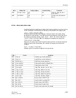
If the voltage transformers are located or line side, the measuring voltages will be
missing when the line is disconnected. To avoid that the undervoltage levels in these
cases are or remain picked up, the current criterion
CURR.SUP.U1<
(address
3768
)
Summary of Contents for siprotec 7SA6
Page 2: ...Siemens Aktiengesellschaft Book No C53000 G1176 C156 2 ...
Page 18: ...xviii 7SA6 Manual C53000 G1176 C156 2 ...
Page 32: ...Introduction 1 14 7SA6 Manual C53000 G1176 C156 2 ...
Page 82: ...Hardware and Connections 2 50 7SA6 Manual C53000 G1176 C156 2 ...
Page 119: ...SIPROTEC 4 Devices 4 25 7SA6 Manual C53000 G1176 C156 2 Figure 4 20 CFC Logic example ...
Page 190: ...Configuration 5 62 7SA6 Manual C53000 G1176 C156 2 ...
Page 652: ...Installation and Commissioning 8 78 7SA6 Manual C53000 G1176 C156 2 ...
Page 724: ...Technical Data 10 56 7SA6 Manual C53000 G1176 C156 ...
Page 800: ...Appendix A 76 7SA6 Manual C53000 G1176 C156 2 ...
Page 866: ...Appendix B 66 7SA6 Manual C53000 G1176 C156 2 ...

