Functions
6-64
7SA6 Manual
C53000-G1176-C156-2
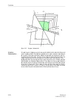
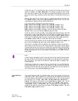
Zone Z1B is usually used in combination with automatic reclosure and/or teleprotec-
tion systems. It can be activated internally by the teleprotection functions (see also
section 6.6) or the integrated automatic reclosure (if available, see also section 6.1) or
externally by a binary input. It is generally set to at least 120% of the line length. On
three-terminal line applications (teed feeders), it must be set to securely reach beyond
the longest line section, even when there is additional infeed via the tee-off point. The
delay times are set in accordance with the type of application, usually to zero or a very
small delay. When used in conjunction with teleprotection comparison systems, the
dependence on the fault detection must be considered (refer to margin heading “Dis-
tance Protection Prerequisites” in Sub-section 6.6.2.
If the distance protection is used in conjunction with an automatic recloser, it may be
determined in address
1357
1st AR -> Z1B
which distance zones are released prior
to a rapid automatic reclosure. Usually the overreaching zone Z1B is used for the first
cycle (
1st AR -> Z1B
=
Yes
). This may be suppressed by changing the setting to
1st AR -> Z1B
equals
No
. In this case the overreaching zone Z1B is not released
before and during the 1
st
automatic reclose cycle. Zone Z1 is always released. The
setting only has an effect when the service condition of the automatic reclose function
is input to the device via binary input “
>Enable ARzones
” (FNo. 383, power system
data 2).
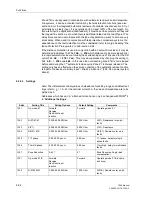
6.2.4.3
Settings
Note:
The indicated secondary values of impedance for setting ranges and default set-
tings refer to I
N
= 1 A. For the nominal current 5 A the values of impedance are to be
divided by 5.
Addresses which have an „A“ attached to its end can only be changed with DIGSI
®
4
in “Additional Settings“.
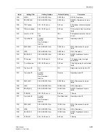
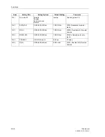
Addr.
Setting Title
Setting Options
Default Setting
Comments
1301
Op. mode Z1
Forward
Reverse
Non-Directional
Inactive
Forward
Operating mode Z1
1302
R(Z1) Ø-Ø
0.050..250.000 Ohm
1.250 Ohm
R(Z1), Resistance for ph-ph-
faults
1303
X(Z1)
0.050..250.000 Ohm
2.500 Ohm
X(Z1), Reactance
1304
RE(Z1) Ø-E
0.050..250.000 Ohm
2.500 Ohm
RE(Z1), Resistance for ph-e
faults
1305
T1-1phase
0.00..30.00 sec;
∞
0.00 sec
T1-1phase, delay for single
phase faults
1306
T1-multi-phase
0.00..30.00 sec;
∞
0.00 sec
T1multi-ph, delay for multi phase
faults
1307
Zone Reduction
0..45
°
0
°
Zone Reduction Angle (load
compensation)
1351
Op. mode Z1B
Forward
Reverse
Non-Directional
Inactive
Forward
Operating mode Z1B (overrre-
ach zone)
1352
R(Z1B) Ø-Ø
0.050..250.000 Ohm
1.500 Ohm
R(Z1B), Resistance for ph-ph-
faults
Summary of Contents for siprotec 7SA6
Page 2: ...Siemens Aktiengesellschaft Book No C53000 G1176 C156 2 ...
Page 18: ...xviii 7SA6 Manual C53000 G1176 C156 2 ...
Page 32: ...Introduction 1 14 7SA6 Manual C53000 G1176 C156 2 ...
Page 82: ...Hardware and Connections 2 50 7SA6 Manual C53000 G1176 C156 2 ...
Page 119: ...SIPROTEC 4 Devices 4 25 7SA6 Manual C53000 G1176 C156 2 Figure 4 20 CFC Logic example ...
Page 190: ...Configuration 5 62 7SA6 Manual C53000 G1176 C156 2 ...
Page 652: ...Installation and Commissioning 8 78 7SA6 Manual C53000 G1176 C156 2 ...
Page 724: ...Technical Data 10 56 7SA6 Manual C53000 G1176 C156 ...
Page 800: ...Appendix A 76 7SA6 Manual C53000 G1176 C156 2 ...
Page 866: ...Appendix B 66 7SA6 Manual C53000 G1176 C156 2 ...


