


Basic Operation
R&S
®
Cable Rider ZPH
34
User Manual 1321.0950.02 ─ 07
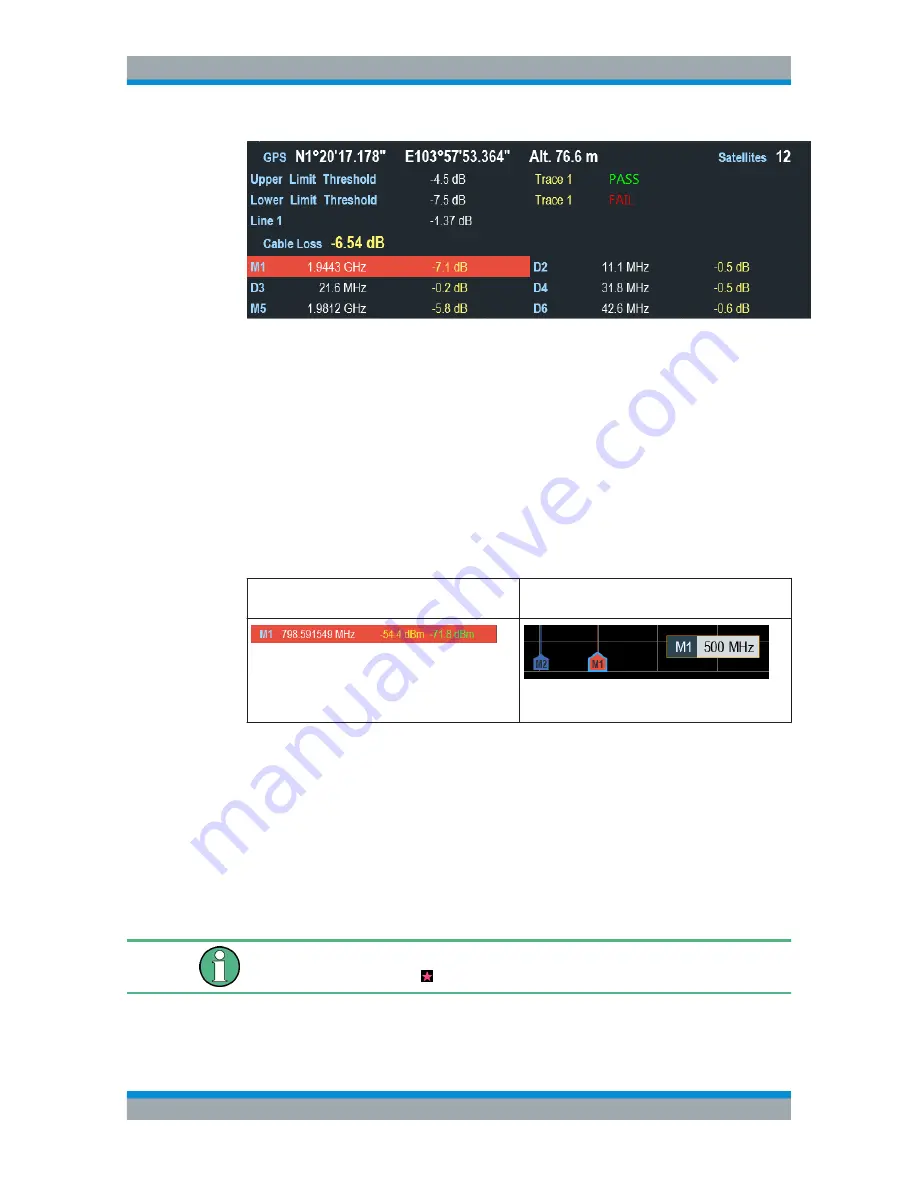
It displays measurement results of the followings:
●
GPS information
●
Cable loss result
●
Display lines value
●
Limit lines result
●
Marker values
When the marker is selected in the "Measurement result view", an entry box for marker
positioning is displayed on the
measurement trace window
. The selected marker is
also highlighted with a blue frame around the marker icon in the "Measurement trace
window".
Table 4-1: Selected marker
Selected marker in the "Measurement result
view"
Selected marker in the "Measurement trace win-
dow"
Note: There is a blue frame around the selected
marker icon, "M1".
For more information on marker measurement, see
Chapter 7.3.2, "Using Markers"
,
on page 157.
4.1.3
Measurement Trace Window
The "Measurement trace window" is the main user interface window in the R&S Cable
Rider ZPH. It displays the measurement traces where markers and limit lines are also
displayed. It also displays the result format, calibation status and internal DC bias set-
ting status.
Invalid trace indicator
Trace invalid indicator icon, indicates that the measurement is still in progress.
Screen Layout and Elements


