CHAPTER 12 INSTALLATION
12-46
COPYRIGHT © 1999 CANON INC. CANON imageRUNNER 400/330 REV.0 JAN. 1999 PRINTED IN JAPAN (IMPRIME AU JAPON)
Switch
SW3-3
SW3-4
SW3-5
SW3-6
Description
Keep it to OFF at all times.
Sets the line setting to push pulse.
Set she line setting to dial pulse.
Sets the dial pulse speed to 20 pps.
Sets the dial pulse speed to 10 pps.
Not used.
Settings
OFF
ON
OFF
ON
OFF
SW3-1
OFF
ON
OFF
ON
Function
Set the modem signal transmission level to -16 dBm.
Sets the modem signal transmission level to -14 dBm.
Sets the modem signal transmission level to -12 dBm.
Sets the modem signal transmission level to -10 dBm.
SW3-2
OFF
OFF
ON
ON
SW3-1
SW3-2
See right.
Table 12-601
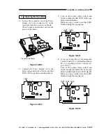
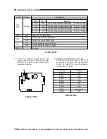
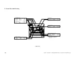
13) Connect the power supply unit to the
power plug, and check to make sure that
LED1 [19] (green) of the board of the
controller turns on.
Figure 12-611
14) Initialize the RAM of the controller.
Set the bits of the DIP switch (SW2) [20]
as shown, and press the push switch
(SW4) [21]. LED5 [22] (red) will turn on
in response to a press.
SW2 bits
SW2-1
SW2-2
SW2-3
SW2-4
SW2-5
SW2-6
SW2-7
SW2-8
Settings
OFF
OFF
ON
ON
OFF
OFF
See step 9).
OFF
Table 12-602
LED1 LED2 LED3
2
1
LED5
LED6
LED4
IC6
SW1
SW4
SW3
6
1
BAT1
CN4
1
2
CN3
CN2
[19]
SW2


