CHAPTER 10 EXTERNALS/AUXILIARY MECHANISMS
10-22
COPYRIGHT © 1999 CANON INC. CANON imageRUNNER 400/330 REV.0 JAN. 1999 PRINTED IN JAPAN (IMPRIME AU JAPON)
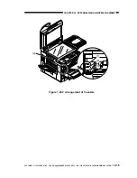
4) Disconnect the two connectors [4] from
the back of the control panel.
Figure 10-515
5) Remove the four screws [6], and detach
the control panel [5].
Figure 10-516
2. Removing the LD PCB, CPU PCB,
and Key Switch PCB
1) Disconnect the three connectors, and
remove the five screws; then, detach the
control panel support plate [1].
Figure 10-517
2) Remove the four screws, and remove the
two flat cables; then, detach the LCD PCB
[2].
3) Remove the four screws, remove the flat
cable, and disconnect the four connectors;
then, detach the CPU PCB [3].
Figure 10-518
[2]
[5]
[6]
[1]
[2]
[3]


