COPYRIGHT © 1999 CANON INC. CANON imageRUNNER 400/330 REV.0 JAN. 1999 PRINTED IN JAPAN (IMPRIME AU JAPON)
9-23
CHAPTER 9 FIXING SYSTEM
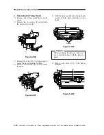
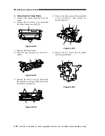
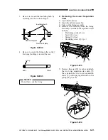
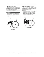
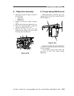
7. Removing the Fixing Assembly
Outlet Sensor
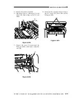
1) Open the front door.
2) Open the delivery assembly.
3) Remove the fixing assembly.
4) Remove the four screws [3], and detach
the fixing assembly inlet sensor connector
cover [1] and the fixing assembly outlet
sensor [2] from the bottom of the fixing
assembly.
Figure 9-226
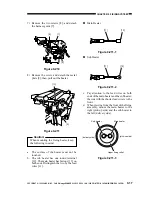
8. Applying Lubricant
Apply heat-resisting grease (CK-0427) to
the parts shown.
Figure 9-227
Engagement of the gears (on flat
teeth; heat-resisting grease)
Edge of gears (lubricant)
Engagement of gears of the fixing
assembly knob (heat-resisting grease)
[8]
[9]
[9]
[7]
[1]
[2]

