CHAPTER 14 TROUBLESHOOTING
14-40
COPYRIGHT © 1999 CANON INC. CANON imageRUNNER 400/330 REV.0 JAN. 1999 PRINTED IN JAPAN (IMPRIME AU JAPON)
3
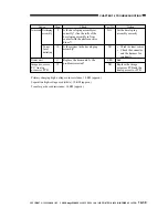
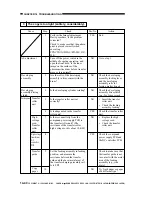
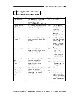
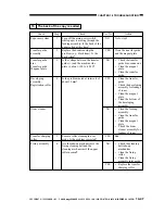
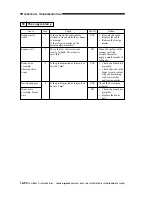
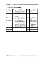
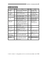
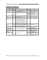
The copy is too light (entirely, considerably).
Cause
AE adjustment
Developing
assembly
Developing
assembly driving
clutch
Action
End.
Go to step 5.
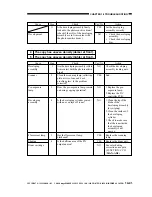
Check the developing
assembly locking lever
and the developing
assembly rolls for
foreign matter (toner).
Check the developing
assembly drive clutch
(e.g., for loose screw).
Insert the transfer
roller unit.
Check the feeding
assembly locking
Check the transfer roller
unit.
Replace the high-
voltage cord.
Check the transfer
roller unit.
Check the compound
power supply PCB and
the DC controller PCB.
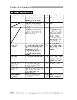
Check to make sure that
the transfer guide is not
in contact with the metal
area of the feeding
assembly (e.g., side
plate).
Try fresh paper or paper
of a different type.
Step
1
2
3
4
5
6
7
8
9
10
Yes/No
YES
NO
NO
NO
NO
YES
NO
YES
NO
Check
Perform the Image Adjustment
Basic procedure. Is the problem
corrected?
Check to make sure that the pattern
print is placed correctly when
executing
FUNCTION>DENS>PD-ME, DZ-
ME.
Turn off the power switch in the
middle of copying operation, and
open the front door. Is the toner
image on the surface of the
photosensitive drum before transfer
more or less normal?
Are the rolls of the developing
assembly in firm contact with the
drum?
Is the developing cylinder rotating?
Is the transfer roller unit set
correctly?
Is leakage noted in the transfer
roller unit?
Is there conductivity from the
compound power supply PCB to
the transfer roller unit? (The
resistance of the transfer roller
high-voltage cord is about 10 K
Ω
)
Set the feeding assembly in feeding
position, and measure the
resistance between the transfer
guide and the base (metal area) of
the transfer charging assembly rail.
Is it 0
Ω
?
Development Transfer
roller
unit
High-
voltage
cord,
Transfer
roller
unit
High-voltage
transformer,
DC
controller
PCB
Transfer
guide
Copy
paper


