CHAPTER 8 PAPER DECK
8-16
COPYRIGHT © 1999 CANON INC. CANON imageRUNNER 400/330 REV.0 JAN. 1999 PRINTED IN JAPAN (IMPRIME AU JAPON)
2. Controlling the Deck Lifter Motor (M102)
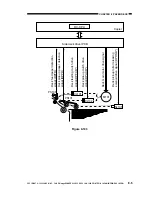
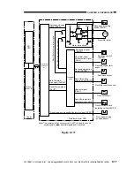
The deck lifter motor control circuit is located on the side deck driver PCB. Figure 8-111 is a
block diagram showing the circuit.
The combination circuit shown in the figure consists of various logic circuits, and serves to
rotate the deck lifter motor clockwise/counterclockwise depending on the combination of the states
of the deck lifer motor drive signal (DLMON*) and the deck lifter up signal (DLUP*) from the
copier's DC-CPU.
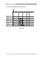
If, for some reason, the deck lifter position sensor (PS104) does not detect the lifter within 60
sec after the deck lifter up signal has been generated, the copier's control panel will indicate
"E041."
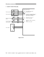
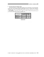
[1] Moving Up the Lifter
The deck is connected to the copier, i.e., the deck set signal (DSET) is '1'.
The deck (compartment) is closed, i.e., the deck open detection signal (DOPND*) is '1'.
The deck (compartment) is closed, i.e., the deck open detecting switch is on.
The deck lifter upper limit signal (DLUL) is '0' and the deck lifter position detection signal
(DLPD) is '0'.
The deck lifter drive signal (DLMON*) is '0'.
The deck lifter up signal (DLUP*) is '0'.
The above conditions cause the lifter to move up.
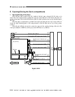
[2] Moving Down the Lifter
The deck (compartment) is open, i.e., the deck open detection signal (DOPND*) is '0'.
The deck lifter lower limit signal (DLLD) is '0' and the deck lifter position detection signal
(DLPD) is '0'.
The deck lifter motor drive signal (DLMON*) is '0'.
The deck lifter up signal (DLUP*) is '1'.
The above condition causes the lifter to move down.

