COPYRIGHT © 1999 CANON INC. CANON imageRUNNER 400/330 REV.0 JAN. 1999 PRINTED IN JAPAN (IMPRIME AU JAPON)
6-19
CHAPTER 6 IMAGE FORMATION SYSTEM
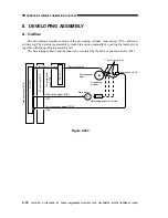
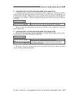
5. Controlling the Level of the Developing Bias DC Component (1)
In memory copying, the laser is driven based on binary image data, which does not have
density information, preventing adjustment with a density correction curve for output images. As
such, the density of images during memory copying is adjusted by varying the developing bias DC
component. (For details, see Chapter 4 "Image Processing and Density Processing in Memory
Copying.")
Related Service Mode
ADJUST>DEVELOP>
DE-OFST
Enter the offset value for the developing bias DC component.
Be sure to enter the value indicated on the service label if you have replaced the composite
power supply PCB.
6. Controlling the Level of the Developing Bias DC Component (2)
The level of the developing bias DC component is switched between image areas and non-
image areas to prevent stray toner inside the machine.
Related Service Mode
ADJUST>DEVELOP>
DE-
DC
ADJUST>DEVELOP>
DE-NO-DC
Enter the bias DC component output for image areas.
Enter the developing bias DC component output for non-image
areas (sheet-to-sheet gap).
Be sure to enter the value indicated on the service label if you have replaced the image
processor PCB or initialized the RAM.

