COPYRIGHT © 1999 CANON INC. CANON imageRUNNER 400/330 REV.0 JAN. 1999 PRINTED IN JAPAN (IMPRIME AU JAPON)
9-15
CHAPTER 9 FIXING SYSTEM
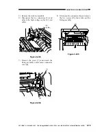
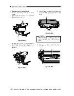
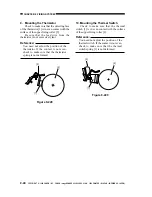
Figure 9-203
7) Remove the screw [7], and detach the
fixing assembly outlet sensor connector
cover [8].
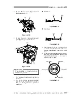
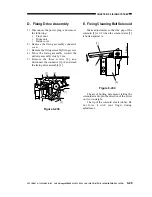
Figure 9-204
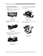
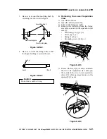
Figure 9-205
[5]
[6]
(red cable)
[7]
[8]
[10]
5) Remove the delivery assembly.
6) Disconnect the two connectors [5], and
detach the high-voltage cable [6] (red
cable).
8) Disconnect the connector [9], and remove
the two screws [10]; then, slide out the
fixing assembly.


