COPYRIGHT © 1999 CANON INC. CANON imageRUNNER 400/330 REV.0 JAN. 1999 PRINTED IN JAPAN (IMPRIME AU JAPON)
3-13
CHAPTER 3 EXPOSURE SYSTEM
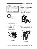
Caution:
The scanning lamp has its own
orientation. Keep the following in mid
when mounting it:
1. Keep the side with the manufacturer's
name to the rear.
2. Keep the transparent side to the
reflecting plate side.
3. Do not touch the transparent section.
Figure 3-504
8) Execute the following in service mode:
FUNCTION>CCD>MAN-ADJ
FUNCTION>DENS (5 items)
2. Removing the Pre-Exposure Lamp
Assembly
1) Remove the drum unit.
2) Remove the inside cover.
3) Remove the screw [2], and disconnect the
connector [3]; then, detach the pre-
exposure lamp assembly [1].
Figure 3-505
B. Scanner Drive Assembly
1. Removing the Scanner Drive Motor
1) Remove the copyboard glass.
2) Remove the rear cover and the rear upper
cover.
3) Remove the flywheel.
4) Remove the two screws [2], and
disconnect the two connectors [3]; then,
detach the RDF connector mount [1].
Figure 3-506
5) Remove the two screws, and disconnect
the two connectors; then, detach the
cooling fan unit [4].
Figure 3-507
Reflecting plate
Transparent section
[3]
[1]
[2]
[2]
[1]
[2]
[3]
[4]
[5]
[6]
[6]

