COPYRIGHT © 1999 CANON INC. CANON imageRUNNER 400/330 REV.0 JAN. 1999 PRINTED IN JAPAN (IMPRIME AU JAPON)
6-3
CHAPTER 6 IMAGE FORMATION SYSTEM
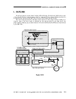
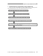
C. Controlling the Primary Charging Roller Bias
1. Outline
The machine uses a charging roller for direct charging. In addition to the DC bias, and AC bias
is applied to the primary charging roller to ensure stable charging. The control items include the
following:
DC bias constant voltage
AC bias constant current
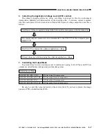
Application voltage level correction (APVC control)
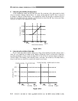
AC bias by environment (humidity) sensor and software counter reading
DC bias by temperature sensor and software counter reading
Figure 6-102
Primary charging
roller
Photosensitive
DC controller PCB
Image processor PCB
Composite power supply PCB
High-voltage
main
transformer
(for DC
component)
Drum temperature
detection
Humidity detection
AC power supply voltage input
Serial communication
DC bias
AC bias
DC-CPU
PW-CPU
Primary charging output enable
signalVPDC*)
Transformer
drive signal
DC bias mode signalHVPH)
AC bias ON signal
AC bias mode signal
AC/DC bias level signal
DC bias voltage value
Measurement value
Measurement value
Current value
(APVC measurement value)
AC bias control signal
DC bias control signal
Voltage
detection
Output
control
High-voltage
transformer for
primary
charging (for AC
component)
Drive
control
Current
detection
J209B
J209B
J103B
J103B
J209A
J103A
drum

