CHAPTER 9 FIXING SYSTEM
9-14
COPYRIGHT © 1999 CANON INC. CANON imageRUNNER 400/330 REV.0 JAN. 1999 PRINTED IN JAPAN (IMPRIME AU JAPON)
A. Fixing Assembly
1. Removing the Fixing Assembly
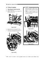
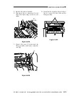
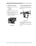
1) Open the front door.
2) Remove the screw [2], and detach the
fixing assembly knob.
Figure 9-201
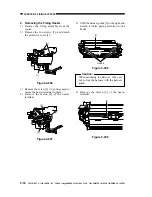
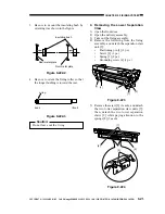
3) Remove the screw [3] (Figure 9-202).
4) Detach the fixing delivery connector
cover [4] as if to displace it upward.
Figure 9-202
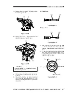
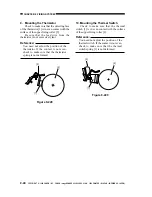
Caution:
When mounting the connector cover,
take care so that its bottom will not
interfere with the spring shown in the
figure.
Take care so that the connector cover
will not interfere with the spring,
displacing the spring.
Figure 9-202-1
[1]
[2]
Lift to detach.
Hooks.
[3]
[4]
Sprig
Connector cover
Spring
Figure 9-202-2

