CHAPTER 9 FIXING SYSTEM
9-24
COPYRIGHT © 1999 CANON INC. CANON imageRUNNER 400/330 REV.0 JAN. 1999 PRINTED IN JAPAN (IMPRIME AU JAPON)
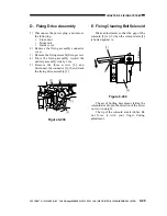
Figure 9-228
9. Mounting the Thermistor
Check to make sure that the detecting face
of the thermistor [1] is in even contact with the
surface of the upper fixing roller [2].
Be sure that the lead wire from the
thermistor is not excessively taut.
Reference:
You need not adjust the position of the
thermistor. If the contact is not even,
check to make sure that the thermistor
spring is not deformed.
Figure 9-229
10. Mounting the Thermal Switch
Check to make sure that the thermal
switch [1] is in even contact with the surface
of the upper fixing roller [2].
Reference:
You need not adjust the position of the
thermal switch. If the contact is not even,
check to make sure that the thermal
switch spring [3] is not deformed.
[3]
[2]
[1]
[3]
[2]
[1]

