COPYRIGHT © 1999 CANON INC. CANON imageRUNNER 400/330 REV.0 JAN. 1999 PRINTED IN JAPAN (IMPRIME AU JAPON)
12-37
CHAPTER 12 INSTALLATION
3
Checking the Operation
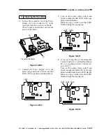
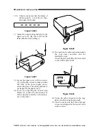
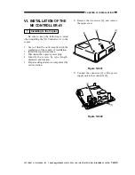
1) Connect the connector [1] of the Power
Supply-A1 to the connector [2] of the
copy data controller correctly as shown.
Check to make sure that the cord is in the
groove of the board.
Figure 12-509
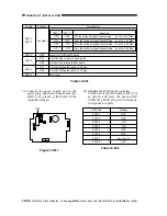
2) Connect the Power Supply-A1 to the
power plug, and check to make sure that
LED1 of the copy data controller turns on.
Figure 12-510
3) Turn on the copier's main switch, and
check to make sure that LED2 of the copy
data controller flashes.
Make one copy to make sure that LED3
flashes during the copying run.
Figure 12-511
4) If you are connecting a Communication
Control board-A1 or an Interface Board-
B1 (i.e., requiring a Power Supply-A1),
go to step 5).
Turn on the copier's main switch, and
check to make sure that LED 1 of the copy
data controller turns on and LED2 flashes.
Make one copy to make sure that LED3
flashes during the copying run.
Figure 12-512
Groove in the board
[1]
[2]
1
6
SW4
SW1 ON
SW5 ON
LED6
LED5
LED4
LED3
LED2
LED1
SW2
SW3
JB2
JB1
JA1
JA2
EPROM
SRAM
CPU
IPC
JC9
JC6
JC5
JC8
J5
1
6
LED1
1
6
SW4
SW1 ON
SW5 ON
LED6
LED5
LED4
LED3
LED2
LED1
SW2
SW3
JB2
JB1
JA1
JA2
EPROM
SRAM
CPU
IPC
JC9
JC6
JC5
JC8
J5
1
6
LED2
LED3
1
6
SW4
SW1 ON
SW5 ON
LED6
LED5
LED4
LED3
LED2
LED1
SW2
SW3
JB2
JB1
JA1
JA2
EPROM
SRAM
CPU
IPC
JC9
JC6
JC5
JC8
J5
1
6
LED1
LED3
LED2


