CHAPTER 10 EXTERNALS/AUXILIARY MECHANISMS
10-14
COPYRIGHT © 1999 CANON INC. CANON imageRUNNER 400/330 REV.0 JAN. 1999 PRINTED IN JAPAN (IMPRIME AU JAPON)
IV. COUNTERS
A. Outline
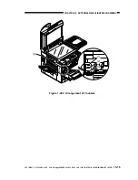
Table 10-401 shows the machine's counter sensors and the counter sensors when the Finisher-
C1/C2 is installed. Figure 10-401 shows the arrangement of the sensors; for the counter operations
according to country, see IV-B.
Name
External delivery sensor (PS7)
Re-pick up sensor (PS9)
Delivery sensor(PI3)
No. 1 paper sensor (PI1A)
Others
Operating conditions
When paper is delivered. (single-sided; 2nd side image of
double-sided)
When paper is picked up (1st side of double-sided)
When a finisher is installed.
When the saddle stitcher function is used.
When paper is picked up (when pick-up roller solenoid turns on;
1st side while a control card is used)
Table 10-401 Counter Sensors
Figure 10-401 Arrangement of Counter Sensors
PS7
PS9
PI3
PI1A


