COPYRIGHT © 1999 CANON INC. CANON imageRUNNER 400/330 REV.0 JAN. 1999 PRINTED IN JAPAN (IMPRIME AU JAPON)
10-11
CHAPTER 10 EXTERNALS/AUXILIARY MECHANISMS
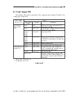
Power supply
generation PCB
Low-voltage
power supply
PCB
Composite power
supply PCB
Destination
Scanner motor, laser scanner motor, side
paper deck (in STBY)
CCD PCB, DC controller PCB, fax PCB, fan
(during half-speed rotation)
Laser driver PCB
Image processor PCB, DC controller PCB,
CCD PCB, cassette pedestal, side paper deck,
fax PCB
Image processor PCB
DC controller PCB, CCD PCB, fax PCB
Fixing motor, main motor, machine DC
load*, cassette pedestal, side paper deck (in
operation), Multi Output Tray-3
Pre-exposure lamp
Fluorescent lamp, primary charging roller,
developing cylinder, transfer charging roller,
transfer guide, separation static eliminator,
fixing bias
Rated output
voltage
+38V
+15V
+7.6V
circuit
name
+8.0V
+5.2V
circuit
name
+5.1V
+3.4V
-12V
+24VU
+24VR
High voltage
Tolerance
38V
+13% -12%**
15V ± 5%
6.2 to 9.2V
5.2V ± 0.1V
3.4V ± 0.1V
-12V ± 5%
-24V ± 10%
-24V ± 5%
B. Power Supply PCB
The machine's DC power is generated on the composite power supply PCB and the low-
voltage power supply PCB.
Table 10-301
Output
* Motor clutch, solenoid, fan, etc.
** At rated load, 38 V ±10%.


