COPYRIGHT © 1999 CANON INC. CANON imageRUNNER 400/330 REV.0 JAN. 1999 PRINTED IN JAPAN (IMPRIME AU JAPON)
7-57
CHAPTER 7 PICK-UP/FEEDING SYSTEM
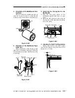
4. Orientation of the Multifeeder Pick-
Up Roller
When mounting the multifeeder pick-up
roller [1], be sure to orient it so that the side
with a cross [2] on the collar is toward the rear.
Figure 7-220
5. Orientation of the Multifeeder Paper
Guide Cam
Make adjustments so that the paper guide
plate cam is as indicate in the figure when the
solenoid plate is in contact with the claw of the
control ring.
Figure 7-221
6. Attaching the Timing Belt to the
Multifeeder
1) Butt the side guide plates of the
multifeeder against both ends (A; open
state).
2) Move the slide volume to the center (in
the direction of B), and attach the timing
belt to the pulley.
Figure 7-222
7. Adjusting the Rear/Front Registration
Make a copy in Direct, and check to make
sure that the margin along the front of the
image is 2.5 ±1.5 mm.
Figure 7-223
[1]
[2]
(rear)
Solenoid plate
Lever
Gear 1
Control ring
Screw w/
hex hole
Gear 2
Paper guide
plate cam
Claw
Timing belt
Pulley
Pulley
Slide volume
Rack plate
A
B
0
2
4
6
8
10
(-)
(+)
2.5±1.5mm


