CHAPTER 2 BASIC OPERATION PROVIDES
2-16
COPYRIGHT © 1999 CANON INC. CANON imageRUNNER 400/330 REV.0 JAN. 1999 PRINTED IN JAPAN (IMPRIME AU JAPON)
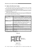
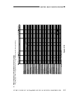
3. Outputs from the DC Controller PCB
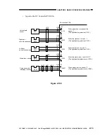
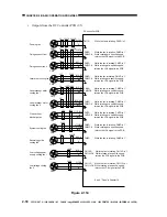
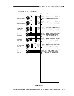
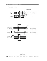
Outputs from the DC Controller PCB (1/5)
Figure 2-112
DC controller PCB
M8
M1
Main motor
Delivery motor
Laser scanner motor
M4
Laser scanner
motor drier
PCB
+5V
+5V
M1D
M1LCK
J102
-B9
-B10
-B11
-B12
J104
-A1
-A2
-A3
J106-10
-11
-8
-9
-12
-13
+24V24V
See I.D. "Controlling the
Main Motor" in Chapter 2.
See IV. "Controlling the Laser
Scanner Motor" in Chapter 5.
J18
M3
Scanner motor
J116
-1
-2
-3
-4
-5
J28
J424B
M2
M2LCK
M2D*
24V
0V
J115
-A5
-A6
-A7
J406
Fixing motor
J441A
J402A
M4LCK
M4D
M6A*
M6A
M6B*
M6B
M7A*
M7A
M7B*
M7B
M8A
M8A*
M8B
M8B*
24V
0V
M6
J22
Lower feeder motor
J410
38V
0V
J114
-B7
-B8
-B9
-B10
M7
J19
Reversal delivery
motor
J403A J107
-A10
-A11
-A12
-A13
J451
J403B

