CHAPTER 8 PAPER DECK
8-14
COPYRIGHT © 1999 CANON INC. CANON imageRUNNER 400/330 REV.0 JAN. 1999 PRINTED IN JAPAN (IMPRIME AU JAPON)
F. Controlling the Deck Motor
1. Controlling the Deck Main Motor (M101)
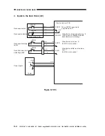
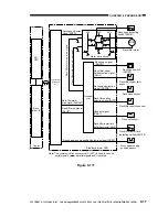
The deck main motor is controlled by the copier's DC-CPU. Figure 8-110 shows the circuit
used to drive the deck main motor, and the circuit has the following functions:
[1] Turning on and off the deck main motor.
[2] Switching the rotation speed of the deck main motor.
a. Turning On and Off the Motor
When the deck main motor drive signal (DMON) from the copier goes '1', the motor drive
circuit goes '0', causing the motor to rotate at a specific speed. When the deck main motor drive
signal (DOMON) goes '0', on the other hand, the motor drive circuit turns off to stop the motor.
The copier's DC-CPU monitors the rotation of the deck main motor with reference to the PLL
lock signal (DMPLK); if, for some reason, the PLL lock signal remains '1' for 900 ms while the
DMON is '1', it will indicate "E043" on the copier's control panel.
Figure 8-110
Deck main motor driver PCB
DC-
CPU
Copier
Side deck
driver PCB
Motor drive
signal
Deck main motor
M101
Encoder
-6
J14
-3
J105
-4
-5
-2
-1
-4
-3
Deck main motor
drive signal (DMON)
Deck main motor PLL
lock signal (DMPLK)
Deck main motor speed
switch signal (DBIT 0)
Deck main motor speed
switch signal (DBIT 1)

